4
Sargent and Greenleaf
Revision 02/15/2022 Document: 630-600
1 - General Information
1.1— About Your Locking System
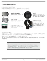
The Model 6128/6129/6106 Electronic Lock has the following hardware components:
6128 /6129 Motorized lock
housed within the safe. Provides for Bank
and Service modes of operation
Keypad
on front of safe door. This is a 12-key
alphanumeric keypad used to enter PIN
codes and programming commands.
6106 Pivot bolt lock
housed within the safe. Provides for Bank
and Service modes of operation
Duress Module (optional)
Housed within the safe. this module
must be connected to the lock to use the
duress alarm feature.
Keypad Extension Base
Installed under the keypad. This is
required when using the lock’s Service
Mode. The extension base provides a
green LED to indicate “Status 1”, and
a red LED to indicate “Status 2” and a
yellow LED to indicate “Mode” of lock
operation. The extension base also
provides a port for communication with
Touch Keys.
Keypad Extension Base
Each time you press a number, letter, or other character on the keypad, it beeps and the keypad’s red LED fl ashes. If there is no beep
or LED fl ash, check the batteries and try again (See section 2.10 — Changing the Batteries).
The # key acts as an enter function and must be used after each code entry.
The * key is used with Programming Command Codes. It may also be used to clear the keypad if there is an input error, by entering
the * key twice.
NOTE:
The lock resonds with different beep sequences to indicate different conditions.
The beeps are indicated in the examples by the symbol
♪
. For example, fi ve beeps
are indicated by
♪♪♪♪♪
. Always wait for each set of beeps to end before entering
another number or letter or you will interrupt the lock’s instructions.


