1. General Information
1.1 About Your Locking System
The S&G Audit Lock 2.0 Electronic Lock has the following hardware components:
•
USB Audit Lock 2.0
– The motor driven lock body (direct drive / pivot
bolt) housed within the container.
•
USB Keypad
– The 12-key alphanumeric keypad, on the front of
the container, that is used to enter
PIN codes and programming commands. The keypad contain three LEDs (red,
green, yellow) and a beeper to indicate the different states of the lock. The
keypad also contains a USB connector that will allow a flash
drive to be connected for audit trail downloads.
Each time you press a number, letter, or other character on the keypad, it beeps
and the keypad’s red LED flashes.
If there is no beep or LED flash, check the batteries and try again (See section
2.10 - Changing the Batteries).
The "#" key acts as an enter function and must be used after each code entry.
The "*" key is used with Programming Command Codes. It may also be used to
clear the keypad if there is an input error, by entering the ‘*’ key twice.
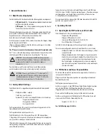
IMPORTANT: The lock responds with different beep sequences
to indicate different conditions. The beeps are indicated in the
examples by the symbol Q. For example, five beeps are
indicated by
.
You should always wait for each set of beeps to end before entering
another number or letter or you will interrupt the lock’s instructions.
1.2 Factory Default Settings
The USB Audit Lock 2.0 is shipped from Sargent & Greenleaf with factory default
settings:
•
Multiple User Mode - enabled
•
Time Delay - zero (0) minutes
• Positions 00, 02, and 10 have default PIN Codes set at the factory:
- Programmer Code 00123456
- Manager Code 02020202
- User Code 10101010
The Programmer Code (PC) can only set-up the operating parameters of the
lock and download the audit trail data.
The Programmer Code cannot open the safe.
The USB Audit Lock 2.0 has the capacity for up to 30 PIN Code positions;
1 Programmer, 3 Managers and 6 Supervisors who manage the lock programs
and up to 20 Users who open and close the lock.
If the lock still has the original S&G factory default settings, you can open the
lock by entering a PIN position and PIN Code, which makes up an 8-digit User
code, followed by the # key.
To open the lock, use the factory setting for PIN position 10, with PIN Code
10101010. Enter: 10101010 # and the lock should open. (If lock does not open
and beep patterns were heard after pressing the # key, reference Section
2.3 “Beep Patterns” to identify condition.)
We recommend that Users change their PIN Codes immediately after the PIN
positions are assigned (Section 3.1).
2. Operating the Lock
2.1 Operating Mode, PIN Positions, and User Codes
The USB Audit Lock 2.0 has the code hierarchy of:
• Programmer (PIN position 00)
• Managers (PIN positions 01, 02, 03)
• Supervisors (PIN positions 04, 05, 06, 07, 08, 09)
• Users (PIN positions 10 through 29)
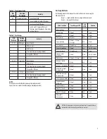
See Table A & Table B beginning on the next page for access privileges.
The lock can be configured to operate in three different User access modes:
• Multiple User mode - any valid code (Supervisor, Manager, or User)
can open the lock.
• Manager/Employee mode - the Managers or Supervisors enable/
disable the access privilege of individual User Codes. When in this
mode the Manager and Supervisor Codes do not open the lock.
• Dual Control mode - two independent User Codes are needed to
open the lock. Manager and Supervisor Codes can be used to open
the lock in this mode.
2.2 PIN Positions and Access Responsibilities
This section defines each PIN position and the respective User functions as
summarized in Tables A & B.
PIN position 00, the Programmer position, can only configure the lock and
download the audit trail.
The Programmer cannot open any locks.
Each User is assigned a 2-digit PIN (Personal Identification Number) position
and an 8-digit PIN Code. The PIN position identifies the type of User
(Programmer, User, etc.) The PIN Code allows the User to access the lock.
Please note that the PIN position is not part of the code that is entered.
Each User can change his own PIN Code but not his PIN position. Users will
always enter their PIN Code, followed by the # key.
Example: 0 2 0 2 0 2 0 2 #
See the following page for tables.
IMPORTANT: You must set the time (11*), set the date (12*)
and start the clock (13*) before audit trail data will contain
a valid time stamp. See Sections 3.1, 3.2 and 3.3. ALSO, the
time and date values must be set at the same time.
4


