-
7
-
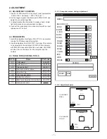
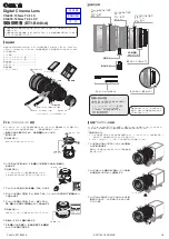
2-3-1. Computer screen during adjustment
2-3-2. Adjustment parts
2. ADJUSTMENT
2-1. ADJUSTMENT CONDITION
1. Use the 5,100K viewer for the subject. (color temperature
: 5500 ± 100 k, luminosity : 1000 ± 100 cd/m )
2. Set the trigger signal of oscilloscope to VIDEO OUT, and
apply H sync unless specified.
3. In adjustments without direction to display charts, shield
light with a lens cap to provide dark condition.
4. Connect the video output to a video monitor with an input
impedance of 75 ohms.
2-2. PREPARATION
1. Install the adjustment software (VHJ-0176) in a computer
running the Windows operating system.
2. Use the adjustment tool (VHJ-0127) to connect the camera
to be adjusted to the serial port (COM1) of the computer
with RS-232C cross cable (Inter link cross cable, VHJ-0149),
and then turn on the power for the computer and the
camera.
2-3. TABLE FOR SERVICING TOOLS
Ref. No.
Name
Part code
J-2
J-3
J-4
VHJ-0126
VHJ-0149
Commander cable (spare)
Adjustment jig
Inter link cross cable
VHJ-0127
J-1
VJ8-0007
Color viewer
J-5
VHJ-0176
Calibration software
J-7
VJ8-0009
Gray scale chart
Color bar chart
VJ8-0010
J-6
Back focus adjustment screwdriver
J-8
Siemens star chart
J-9
VHJ-0178
R GAIN
R HUE
B GAIN
B HUE
Y GAIN
WDD
VHJ-0176
0
0
0
0
0
AUTO
START
END
CLOSE
SYNC
BURST
0
0
A. IRIS
M/WB1
MODEL
BACK FOCUS
0
0
M/WB2
PHASE
0
STATUS
IRIS
0
2
CA-2 BOARD
SIDE A
CA-2 BOARD
SIDE B
CN205
IC241
CT232
TP232
CN203
CT211
TP221
CN201
IC211

