background image

-

 3

 -

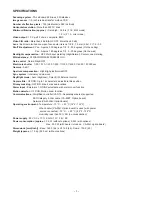
Scanning system : 

PAL standard 625 lines, 50 fields/sec.

Image sensor : 

1/4-inch Interline transfer method CCD

Number of effective pixels : 

752 (Horizontal) x 582 (Vertical)

Horizontal resolution : 

More than 520 TV lines

Minimum illumination (approx.) : 

Gain high : 0.06 lx (F 1.9, B/W mode)

Minimum illumination (approx.) : 

Gain high : 

1.2 lx (F 1.9, color mode)

Video output : 

1.0 Vp-p/75 ohms, composite, BNC

Video S/N ratio : 

More than 48 dB (AGC OFF: More than 50 dB)

Lens : 

Built-in motorized zoom pan focus auto iris lens, f=2.8 - 7.3 mm (2.6x), F=1.9 - 3.0

Pan/Tilt adjustment : 

Pan : Approx. 330 degrees, Tilt : 0 - 90 degrees (On the ceiling)

Pan/Tilt adjustment : 

Pan : Approx. 180 degrees, Tilt : 0 - 90 degrees (On the wall)

Backlight compensation : 

OFF, Multi-spot metering (High/Normal), Center zone metering

White balance : 

ATW/AWC/MWB/3200/5600/FLUO

Gain control

 : Normal/High/OFF

Electronic shutter

 : 1/50, 1/120, 1/250, 1/500, 1/1000, 1/2000, 1/4000, 1/10000 sec.

Gamma : 

0.45/1

Aperture compensation : 

High/High plus/Normal/OFF

Sync system : 

Internal sync/Line lock

Day/Night mode : 

Auto (High/Low), Color, B/W, External control

Camera title : 

OFF/ON, Up to 16 characters, adjustable title position

Privacy masking : 

OFF/ON, Max. 4 masked locations

Alarm input : 

External x 1, NO/NC selectable, with alarm zoom function

Motion detector : 

OFF/ON, Motion zoom function

Communications : 

Simplified controller (VAC-70: Separately ordered) supported

Communications : 

SSP/Category 5 LAN cable  (VA-50ST: Option board)

Communications : 

Network (VA-50LAN: Option board)

Operating environment : 

Temperature: -10 °C - + 50 °C (14°F - 122°F)

                                          When heater (VA-50H: Option board) is used (with power

                                           source connected): -30 °C - + 50 °C (-22°F - 122°F)

Operating environment :


Humidity: less than 90 % RH (no condensation)

Power supply : 

24 V AC ± 10 %, 50 Hz/ 12 V -15 V DC

Power consumption (approx.)

 : 3.5 W (without options), 9.5 W (with options)

Power consumption (approx.)

 : 

Max. 23.0 W (with heater turned on : VA-50H, option board)

Dimensions [mm/(inch)] : 

Base: 162.0 (6.4) x H114.8 (4.5), Dome: 100.5 (4.0)

Weight (approx.) : 

1.5 kg (52.9 oz) (without options)

SPECIFICATIONS

Содержание VDC-DP7585P

Страница 1: ...esignated by a symbol in this schematic diagram designates components whose value are of special significance to product safety Should any component designated by a symbol need to be replaced use only the part designated in the Parts List Do not deviate from the resistance wattage and voltage ratings shown PRODUCT SAFETY NOTICE RoHS This product does not contain any hazardous substances prohibited...

Страница 2: ...ivalent and which lets you adjust the tip temperature up to 450 C 842 F It should also have as good temperature recovery characteristics as possible Set the temperature to 350 C 662 F or less for chip components to 380 C 716 F for lead wires and similar and to 420 C 788 F when installing and removing shield plates The tip of the soldering iron should have a C cut shape or a driver shape so that it...

Страница 3: ...10000 sec Gamma 0 45 1 Aperture compensation High High plus Normal OFF Sync system Internal sync Line lock Day Night mode Auto High Low Color B W External control Camera title OFF ON Up to 16 characters adjustable title position Privacy masking OFF ON Max 4 masked locations Alarm input External x 1 NO NC selectable with alarm zoom function Motion detector OFF ON Motion zoom function Communications...

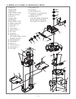
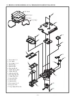
Страница 4: ...x 4 10 Rotate of 90 degrees 11 Hook onto the projection 12 Spacer camera 13 Rotate of 90 degrees 14 CA 4 board 15 Assy wire 5 pins CN406 16 Assy wire 2 pins CN403 17 Assy wire 3 pins CN401 18 FFC 18 pins CN405 19 FFC 16 pins CN404 20 Fixer FFC When reassembling shape the FFC as shown in the diagram 21 Screw 3 x 6 22 Stopper wheel 23 Spring wheel 24 Bearring support wheel 25 Screw 3 x 6 26 Pipe 9 1...

Страница 5: ...rs 14 Three screws 2 x 4 15 CA 4 board 16 Spring lock 17 Two screws 3 x 6 When reassembling provision ally tighten the screws 18 Latch chassis base 19 Chassis base P 20 Screw 2 x 4 21 Three screws 2 x 4 22 Two screws 2 x 4 23 CA 2 board 1 2 3 4 5 6 7 9 8 10 11 12 11 13 14 15 16 17 18 19 24 Two screws 2 x 4 25 CA 3 board 26 Chassis camera PFL 27 Two screws 1 4 x 5 Remove the adhesive in five places...

Страница 6: ...g filter IR 7 Optical dummy glass 8 Optical filter IR 9 Holder optical filter 10 Mounting filter LPF 11 Optical filter PO 12 Gear action DN 13 Gear ider DN 14 Gear ider DN 15 Two screws 1 4 x 5 16 Assy motor DN 17 Assy chassis DN mecha 1 3 BOARD LOCATION REMOVAL OF CA 1 BOARD AND HOLDER OPTICAL FILTER CA 1 Board CA 2 Board CA 3 Board CA 4 Board ...

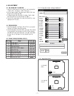
Страница 7: ...ustment tool VHJ 0127 to connect the camera to be adjusted to the serial port COM1 of the computer with RS 232C cross cable Inter link cross cable VHJ 0149 and then turn on the power for the computer and the camera 2 3 TABLE FOR SERVICING TOOLS Ref No Name Part code J 2 J 3 J 4 VHJ 0126 VHJ 0149 Commander cable spare Adjustment jig Inter link cross cable VHJ 0127 J 1 VJ8 0007 Color viewer J 5 VHJ ...

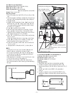
Страница 8: ... the WIDE direction and zooms to the TELE direction The mode switches between COLOR and B W modes each time is pressed 5 Press to set the zoom to WIDE 6 Insert the back focus adjustment screwdriver into the focus adjustment hole and turn it to adjust the focus 7 Tighten the focus adjustment fixing screw to secure the lens Tightening torque 0 08 0 10 N m 8 Press to set the zoom to TELE and check th...

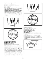
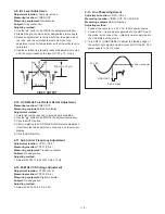
Страница 9: ... in the adjustment window Adjust by operating level scroll bar so that the luminescent spot representing white is overlapping with the crosshair mark in the center of the vectorscope 2 7 Hue and Chroma Adjustment Adjustment location Computer screen Measuring location VIDEO OUT Measuring equipment Oscilloscope vectorscope Subject Color bar chart 1 Use the button to be R GAIN in the adjustment windo...

Страница 10: ...ect Detect adjustment it comfirms that white point can not be seen on the monitor display 5 Click the END button 2 11 Sub Carrier Frequency Adjustment Adjustment location CT211 CA 2 Measuring location TP221 CA 2 Measuring equipment Frequency counter Subject No designation Adjusting method 1 Adjust with CT211 to 4433619 Hz 10 Hz 2 12 28 MHz VCO Voltage Adjustment Adjustment location CT232 CA 2 Meas...

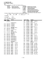
Страница 11: ... Z 25V C1010 403 283 6309 CERAMIC 1U Z 10V C1011 403 283 6309 CERAMIC 1U Z 10V C1012 403 346 2309 CERAMIC 0 1U K 10V C1013 403 346 2309 CERAMIC 0 1U K 10V C1014 403 346 2309 CERAMIC 0 1U K 10V C1015 403 346 2309 CERAMIC 0 1U K 10V C1016 403 285 6901 TA SOLID 22U M 6 3V C1021 403 346 2309 CERAMIC 0 1U K 10V C1022 403 364 5306 CERAMIC 2 2U K 6 3V C1024 403 346 2309 CERAMIC 0 1U K 10V C1025 403 378 3...

Страница 12: ...D 4 7U M 6 3V C2107 403 346 2309 CERAMIC 0 1U K 10V C2108 403 346 2309 CERAMIC 0 1U K 10V C2109 403 346 2309 CERAMIC 0 1U K 10V C2110 403 346 2309 CERAMIC 0 1U K 10V C2111 403 285 3603 TA SOLID 4 7U M 6 3V C2112 403 346 2309 CERAMIC 0 1U K 10V C2113 403 346 2309 CERAMIC 0 1U K 10V C2114 403 346 2309 CERAMIC 0 1U K 10V C2115 403 285 6802 TA SOLID 10U M 6 3V C2118 403 285 3603 TA SOLID 4 7U M 6 3V C...

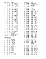
Страница 13: ...DE DSH015 TLEP D3102 407 236 0901 DIODE DSH015 TLEP D3301 407 206 5509 ZENER DIODE UDZS9 1B OSCILLATOR X3001 645 055 5282 OSC CRYSTAL 17 734475MHZ INDUCTORS L3001 645 003 9539 INDUCTOR 39U J L3002 645 003 9386 INDUCTOR 10U J L3101 645 003 9386 INDUCTOR 10U J L3102 645 040 8069 INDUCTOR 1 2U J L3103 645 003 9546 INDUCTOR 47U J L3104 645 040 8069 INDUCTOR 1 2U J CAPACITORS C3001 403 382 2905 ELECT10...

Страница 14: ... 30 D4102 407 251 2201 DIODE RF001M2S OR 407 239 5002 DIODE RF071M2S PMDU D4103 407 251 2201 DIODE RF001M2S OR 407 239 5002 DIODE RF071M2S PMDU D4105 407 251 2201 DIODE RF001M2S OR 407 239 5002 DIODE RF071M2S PMDU D4107 407 251 2201 DIODE RF001M2S OR 407 239 5002 DIODE RF071M2S PMDU D4108 407 251 2201 DIODE RF001M2S OR 407 239 5002 DIODE RF071M2S PMDU D4110 407 251 2201 DIODE RF001M2S OR 407 239 5...

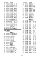
Страница 15: ...502 401 105 0702 MT GLAZE 100K JA 1 16W R4503 401 105 1204 MT GLAZE 120K JA 1 16W R4521 401 105 4502 MT GLAZE 390 JA 1 16W R4602 401 105 0504 MT GLAZE 1K JA 1 16W R4603 401 105 0504 MT GLAZE 1K JA 1 16W R4604 401 105 0504 MT GLAZE 1K JA 1 16W R4605 401 105 7909 MT GLAZE 0 000 ZA 1 16W R4606 401 105 7909 MT GLAZE 0 000 ZA 1 16W R4612 401 105 7909 MT GLAZE 0 000 ZA 1 16W R4613 401 105 7909 MT GLAZE ...

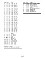
Страница 16: ...HOLDER 6410 613 207 9846 ARM CAMERA TILT PFL N S P 6420 613 207 9860 ARM CAMERA PAN PFL N S P 6440 613 209 0964 FIXER FFC 6450 613 209 2388 LATCH CHASSIS BASE 6455 613 209 3750 SPRING LOCK 6460 613 200 4800 PIPE 6470 613 209 3248 STOPPER WHEEL 6480 613 209 3200 SPRING WHEEL 6490 613 209 3187 BEARING SUPPORT WHEEL CA4 613 207 9259 COMPL PWB CA 4 CN003 610 227 9771 SOCKET BNC NJ600 411 030 5406 SCR ...

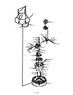
Страница 17: ...2 5130 NJ630 6460 NJ630 6460 6050 NJ620 6470 NJ620 6420 6410 NJ620 6440 6480 6470 NJ620 6480 6490 NJ620 6490 6480 6470 6002 NJ620 6490 6070 1 N S P NJ600 6450 6040 6455 NJ620 6080 CA4 6080 NJ600 NJ600 6080 CN003 W4003 ...

Страница 18: ...208 6189 ASSY CHASSIS DN MECHA 6301 613 208 6165 GEAR ACTION DN 6302 613 199 2610 GEAR IDER DN 6303 613 208 6233 HOLDER OPTICAL FILTER 6304 613 208 6905 MOUNTING FILTER LPF 6305 613 208 7377 MOUNTING FILTER IR 6306 613 208 6196 SHIELD LID FILTER 6307 613 208 6202 SHIELD LID GEAR 6320 645 084 4027 ASSY MOTOR DN 8000 645 084 1330 OPTICAL DUMMY GLASS 8001 645 084 1316 OPTICAL FILTER IR 8002 645 084 1...

Страница 19: ...19 NJ650 6303 6307 6305 8001 6320 NJ650 6200 8002 6304 6014 6012 NJ650 6302 6301 6306 6302 8000 CA1 NJ610 2 CA3 8000 6000 CA2 NJ650 NJ600 NJ600 NJ600 NJ650 1 NJ600 2 6004 IC101 ...

Страница 20: ...Mar 06 SANYO Electric Co Ltd Osaka Japan Printed in Japan ...

Отзывы: