LENS ADJUSTMENT
The camera comes pre-adjusted and ready to install at time of
factory shipment, but you may want to make adjustments or
settings to adapt to the operating conditions or installation
environment.
Loosen the four camera cover fixed screws, and then remove the
camera cover. When you have finished adjusting, reinstall the
camera cover. Refer to
1
in “PARTS NAMES AND FUNCTIONS”.
If you have trouble adjusting the camera, consult your dealer or a
Sanyo Authorized Service Center.
(
◆
= Factory default setting)
1
1
1
1
Outline compensation (Aperture)
2
2
2
2
Gain control
For adjusting the sensitivity of the camera. Use this setting for
shooting in dark environments.
3
3
3
3
Backlight compensation (Multi-spot metering)
When applying backlight compensation to the
entire screen.
Note:
If the background of the object is extremely dark, the center of the
object may be too bright. In this case, set the center-weighted
metering mode (
4
).
4
4
4
4
Backlight compensation (Center-weighted metering)
When applying backlight compensation to
only the center of the screen.
5
5
5
5
Color compensation (White balance)
6
6
6
6
Sync setting
7
7
7
7
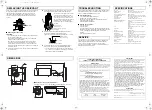
Lens iris dial
If the entire image is too dark or too bright, adjust the dial (VR301).
8
8
8
8
Electronic Shutter speed setting
A combination of the 2 switches can be used to set up to 4 speed
levels.
Note:
Using the high speed electronic shutter indoors with low lighting,
will give darker pictures. In such a case, add some lights to make
sure the lighting is sufficient.
9
9
9
9
Color/Black-and-White switching level
This camera has a built-in Day/Night function that automatically
change the mode between color for high luminance situations such
as during the day and black-and-white for low luminance situations
such as at night. This allows the camera to be used in a wide
range of luminance conditions.
This switch is used to set the timing for automatic switching
between the color screen and the black-and-white screen based
on surrounding brightness.
The color screen will be displayed first of all when the power is
turned on.
Note:
• When switching between color and black-and-white screens
automatically, it is normal for movement of the optical filter to be
heard and for a vertical black band to move across the screen.
• Switching from black-and-white to color may occur if there is a
significant degree of reflection from the object when using
infrared illumination in black-and-white mode. Adjust the
illumination to avoid switching to color mode.
• The focus setting position may differ between color and black-
and-white screens. Carry out adjustment to ensure that the
focus for both screens is in the optimum position.
(Sharp)
Emphasizes object outlines.
(Soft)
◆
◆
◆
◆
Normal setting
(High)
Increased sensitivity allows shots to be
taken in dark environments.
(Low)
◆
◆
◆
◆
Normal setting
(Multi)
The entire screen is divided in the metering
area (
), and each area is metered and
backlight-compensated.
(Off)
◆
◆
◆
◆
This function is off.
ON
ON
1
2
3
1
2
3
4
5
6
VR302 VR303
VR301
VR322
1 2 3 4
5
6
8
9
7
1
1
2
2
3
3
(Center)
Only the center of the screen is metered and
backlight-compensated.
(Off)
◆
◆
◆
◆
This function is off.
(Manual)
Lets you fine-tune the white balance
manually.
Turn clockwise to augment screen
red.
Turn clockwise to augment screen
blue.
(Auto)
◆
◆
◆
◆
Compensation is performed automatically.
(Line-lock)
(Only when using a AC 24 V adapter)
Synchronizes the unit with power frequency.
When two or more cameras are connected,
the image displayed on the monitor may roll
vertically. Adjust the phase.
• If using this camera as the second or
subsequent camera;
Adjust the roll by turning this
phase adjustment dial.
• If using this camera as the first
camera;
Adjust the roll by turning the phase
adjustment dial on the second and
subsequent cameras.
(Internal)
◆
◆
◆
◆
Internal Sync
Counter-
clockwise
Closes the lens iris, making the entire
image darker.
Clockwise
Opens the lens iris, making the entire
image brighter.
4
4
5
VR302
VR303
5
6
VR322
6
VR301
Shutter
speed
1/60
◆
◆
◆
◆
1/100
1/1000
1/2000
Switches
(High)
Sets bright switching
(Low)
◆
◆
◆
◆
Normal setting
1
2
1
2
1
2
1
2
3
3
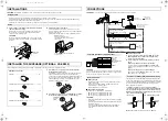
ADJUSTMENTS
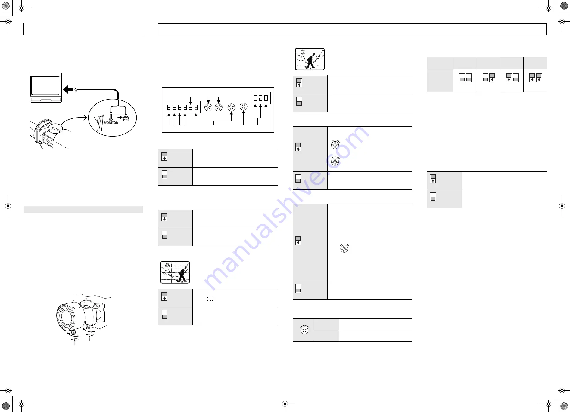
HINT:
• You can use the MONITOR pin and the ground screw to display
an image on a monitor when setting up the camera; the
surveillance angle and range, the lens focus, etc.
Connect a monitor to the MONITOR pin and to the ground
screw using alligator clip cables.
• When monitoring lighting or other extremely bright objects
(which exceed the maximum required illumination), smearing
may occur in the vertical or horizontal direction (either above
and below the high-brightness object or as a perpendicular
band). In such a case, adjust the angle of illumination and other
factors while observing the monitor.
• If fluorescent lighting is used where the camera is installed, the
object will flicker as a result. This type of phenomenon can be
received by replacing the fluorescent lighting with incandescent
lamps.
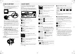
1
Loosen the four screws at the front of the camera, and
then remove the camera cover.
Refer to
1
1
1
1
in “PARTS NAMES AND FUNCTIONS”.
2
Loosen the zoom ring knob, and turn the zoom ring to
zoom in or out (increase or decrease the size of the object
in the frame).
3
Loosen the focus ring knob, and turn the focus ring to
focus the object.
• When you have finished adjusting the zoom and focus, tighten
the zoom and focus ring knobs securely and reinstall the
camera cover.
CAUTION:
Take care not to touch or scratch the lens surface (front lens) when
making adjustments.
Zoom and focus adjustment
2
3
( !"#$%#&


