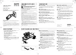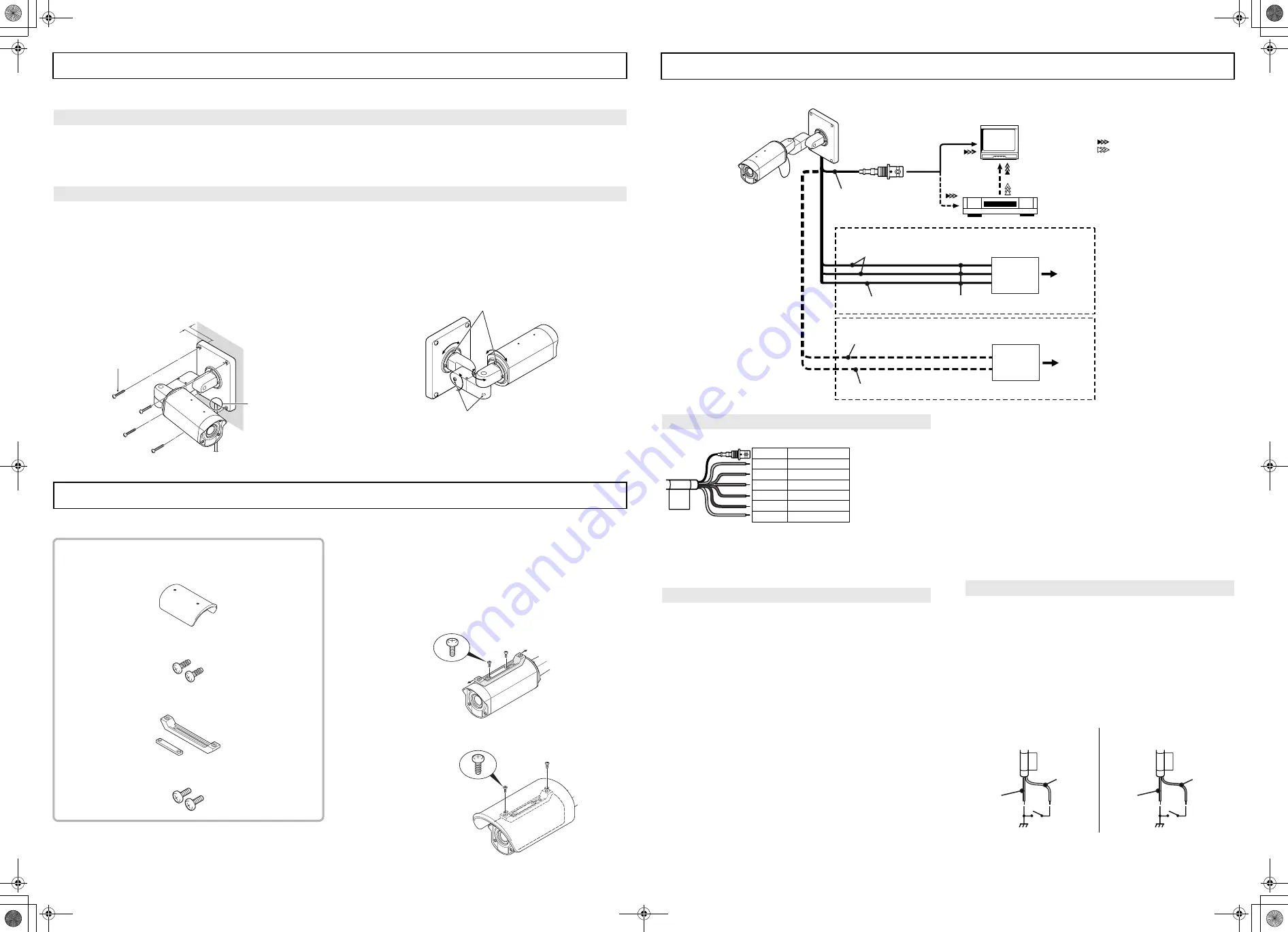
Connection
cord hole
Mounting screw
3 cm or more in
INSTALLATIONS
CONNECTIONS
CAUTION:
Check that the installation location is strong enough to bear the camera before proceeding.
• Install in a location (such as underneath overhangs) that is not exposed to direct sunlight.
If direct sunlight way shine onto the camera at times (depending on the angle of the sun), install the sunshade (Optional; VA-SS400).
• Install to a wall or ceiling with no unevenness in its surface.
If installing to a curved surface, round pillar or similar, use a special bracket (sold separately).
Setup location
Setup
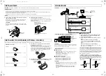
1
Use mounting screws (M8x4, sold separately) to install the
camera to the wall or ceiling.
If routing the connection cord outside the wall, install so that
the connection cord hole is facing downward, and pull the
connection cord out from the hole.
CAUTION:
Be sure to embed the mounting screws at least 3 cm into the
wall. If the screw holes are too shallow, the camera mount may
fall down.
2
Adjust the position of the camera.
Use the hexagon wrench (large, accessory) to loosen the
screws at the place that you want to move, and then adjust the
direction of the camera.
After making the adjustment, securely re-tighten the screws.
Maximum 90 degrees
(to prevent cord from twisting)
Screw tightening torque after adjustment:
2 N·m or more
Screw tightening torque after adjustment:
4.3 N·m or more
CAUTION:
Do not connect the power cable until all other connections have been completed.
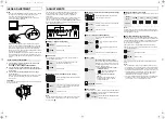
(Video signal)
VIDEO IN
VIDEO OUT
BLACK (VIDEO) cable
RED and BROWN (AC 24 V) cable
WHITE (GND) cable
BROWN (DC 12 V, –) cable
GND
DC 12 V
AC 24 V
TV monitor
(sold separately)
Fig.1 AC 24 V connection
Fig. 2 DC 12 V connection
RED (DC 12 V, +) cable
+
–
~
~
Power adapter
18AWG
Power adapter
Into a
wall
outlet
Into a
wall
outlet
Digital video recorder or
Time-lapse VCR
(sold separately)
1
2
CAUTION:
If part of the copper section of a wire is exposed after a cable has
been connected, trim the end of the wire so that no copper section
is exposed in order to prevent short-circuits.
■
■
■
■
What you need
• Peripheral equipment (such as monitor, digital video recorder
or time-lapse VCR)
• Cables for connecting peripheral equipment and camera
(coaxial cables, connecting plugs)
• Power adapter (AC 24 V or DC 12 V)
■
■
■
■
Supported coaxial cables
You can use any of the following coaxial cables:
• RG-59U (3C-2V) Length: About 250 m max.
• RG-6U (5C-2V)
Length: About 500 m max.
• RG-11U (7C-2V) Length: About 600 m max.
CAUTION:
• When suing an RG-59U (3C-2V) cables, do not use it on piping
or air wiring.
• Select the cable according to the distance between the devices
you wish to connect.
• If you use a cable other than the types above, the image or
sync signal will be attenuated and will not be transmitted
correctly.
■
■
■
■
Making connections
1
Connect the video output connector (BNC type) of the
BLACK (VIDEO) cable to the monitor or digital video
recorder (or time-lapse VCR).
2
Connect the power cable to a power adapter or similar
device.
• When connecting to an AC 24 V power adapter:
Connect all three of the RED, BROWN and WHITE (GND)
cables. There is no difference b and
−
connections.
(Fig. 1)
• When connecting to a DC 12 V power adapter:
Be sure to connect the BROWN cable to the
−
side and the
RED cable to the + side. (Fig. 2)
This camera has a built-in Day/Night function that automatically
change the mode between color for high luminance situations such
as during the day and black-and-white for low luminance situations
such as at night. This allows the camera to be used in a wide
range of luminance conditions.
To manually set the mode to color or black-and-white,
connect each cable to the control terminal as indicated below.
You can adjust the image by remote control. While the Day/
Night function is performed automatically, you can not set to
color or black-and-white manually.
Note:
The maximum length of cable is 600 m (AWG24).
Color lead wire and Color display label
Basic connection
BLACK
YELLOW
BLUE
GRAY
RED
BROWN
WHITE
VIDEO
COLOR
B/W
COMMON
AC24/DC12 V (+)
AC24/DC12 V (–)
GND
Color cable
Black-and-White cable
Ground cable
Power
cable
Video output
connector
Connection for COLOR or B/W (black-and-white) setting
YELLOW
(COLOR)
GRAY
(COMMON)
BLUE
(B/W)
GRAY
(COMMON)
COLOR setting
B/W (black-and-white) setting
If direct sunlight may shine onto the camera at times (depending on the angle of the sun), install the sunshade.
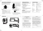
INSTALLING THE SUNSHADE (OPTIONAL; VA-SS400)
1
Use the two accessory screws to install the sunshade
mounting bracket (accessory).
Determine the position of the sunshade so that it will protect
from direct sunlight as much as possible, and adjust the
position of the sunshade mounting bracket back and forth while
the screws are still loose (adjustment range: 30 mm). After
adjusting the bracket position, securely tighten the screws.
(Tightening torque: 0.5 N·m or more)
2
Use the two accessory screws (self-tapping type) to install
the sunshade. (Tightening torque: 0.5 N·m or more)
Sunshade accessories
Sunshade........................................................................ 1 pc
Sunshade mounting screws (Self-tapping type) ........... 2 pcs
Sunshade mounting bracket .......................................... 1 set
Sunshade mounting bracket screws ............................. 2 pcs
Self-tapping
screw for
plastic
! "#$%&

