background image

- 26 -


16.  Actions and settings after reset 


Actions and settings when a power is supplied (Power on reset) 


Alarm Off 
Compressor Off 
Remote alarm 

Off 

Ring Back 

30 minutes 

Door alarm delay time 

2 minutes 

Timer Reset 
2H, 8H timer 

Reset (0) 

Counting time during compressor L is inactive 

Reset 

Setting data 

Read by non-volatile memory 


  Momentary power interruption: 


          When a chamber temperature is lower than set temp10

, it is diagnosed that unit is 

in momentary power interruption.   


  Actions and settings after unit retrieves from power failure alarm: 


Alarm Off 
Compressor Off 
Remote alarm 

On 

Door alarm delay time 

2 minutes 

Timer Reset 
2H, 8H timer 

Reset (0) 

Counting time during compressor L is inactive 

Reset 

Setting data 

Read by non-volatile memory 


17.  Lamp and display 


 Lamp 

specifications: 


     <Control PCB> 

Lamp 

Color 

Lamp status 

Unit status 

On 

Not in alarm 

DP1 Orange 

Off 

High/low temp. alarm, sensor failure, power failure 

On 

Compressor L is active 

DP2 Green 

Off 

Compressor L is inactive 

On 

Capillary heater is active 

DP3 Red 

Off 

Capillary heater is inactive 

DP4 (Unused) 

On 

Compressor H is active 

DP6 Green 

Off 

Compressor H is inactive 

 
    <Display PCB> 

Lamp 

Color 

Lamp status 

Unit status 

DP51 Red 

Flash  Alarming 

DP52 

Green 

On 

Status 1 or 2 or 3 is occurred 

DP53 

Orange 

On 

Filter alarm is occurred 

DP54 

Red 

On 

Door is ajar 

On 

Notice of battery life 

DP55 Orange 

Flash 

Notice of fan motor life 

DP56 (Unused) 


Содержание MDF-U55V

Страница 1: ...Service Manual Ultra Low Temperature Freezer SANYO Electric Co Ltd Biomedical Business Division MDF U55V SM9910253 FILE No ...

Страница 2: ...Effective models This service manual is effective for following model Model Product code Voltage and Frequency MDF U55V 823 029 54 230 240V 50Hz ...

Страница 3: ... 䞉Specification of sensor 1 0 䞉Wiring diagram 1 1 䞉Circuit diagram 1 2 䞉Control specifications 1 3 䞉Parts layout 2 8 䞉Test data 3 0 P u l l d o w n P u l l u p d a t a P u l l d o w n t e m p e r a t u r e s P u l l d o w n p r e s s u r e P u l l d o w n c u r r e n t i n p u t T e m p e r a t u r e u n i f o r m i t y 1 7 p o i n t s m e a s u r e d A m o u n t o f p o w e r c o n s u m p t i o ...

Страница 4: ... High stage side䠖Fin and tube type Low stage side䠖Cascade condenser Refrigerant High stage side䠖R 404A Low stage side䠖R 508 Refrigerating oil Ze NIUSL22SA Oil additive n pentane Oil separator SPK 0S02S2 Shelf Stainless steel 3 shelves adjustable Inner dimension䠖W 608 㽢 D 535 mm Load䠖50 kg shelf Outer door latch 1pc Outer door lock 1pc Caster 4pcs 䠄leveling leg 2pcs in front side䠅 Access port 䃥17mm...

Страница 5: ...Power failure alarm ALARM lamp blinks and buzzer sounds intermittently Remote alarm activates Remote alarm Allowable contact capacity䠖DC30V 2A䚸N C COM䠈N O COM When temperature alarm or power failure alarm is occurred or any sensor is failed remote alarm contact turns over Notice of battery life BATTERY lamp illuminates when battery accumulation time 2 8 years expires Notice of condensing fan motor...

Страница 6: ...bstitution for pressure switch Compressor delay time Range 3 15 minutes Unit 1minute It is not settable delay time individually between H side compressor and L side compressor Performance specifications Item Specifications Maximum cooling performance 86䉝 at the center of the chamber 䠄AT䠖30䉝䚸No load䠅 Temperature control range 䠉50䉝 to 䠉86䉝 䠄AT䠖30䉝䚸No load䠅 Power source 230V 50Hz 240V 50Hz Rated powe...

Страница 7: ... 4 Side Front Top Back side exit of power cord Inner dimensions of tray Inner dimensions of tray Dimensions ...

Страница 8: ...r Frame pipe Compressor L EX tank Capillary tube EX Oil separator Pre condenser Condenser Dryer H Check valve Accumulator Capillary tube H Suction heat exchanger Cascade condenser Header Dryer H Evaporator Capillary tube L H side L side Refrigeration circuit ...

Страница 9: ...ndenser Condenser P6 35㽢3lines㽢12 columns Fin 38pcs Coil pipe 䃥6 35mm Pre condenser W250 mm 䇷 Frame pipe 䃥4 76 mm 䇷 Evaporator 䠄Type䠅 Cascade condenser Shell and tube 䃥80 mm Tube on sheet type 䃥9 52 mm Accumulator 䃥38 mm Capillary tube Ex capillary Resistance 0 765MPa 0 343MPa 34psi Length L 2000 mm 2500 mm 500 mm Outside diameter OD 䃥2 0 mm 䃥2 0 mm 䃥2 4 mm Inside diameter ID 䃥0 9 mm 䃥0 9 mm 䃥1 2 ...

Страница 10: ... 480 option MTR L03 option CN9 1 2 H comp relay CN4 1 2 Temp control relay 3 4 Heater relay CN3 Remote alarm terminal 1 COM 2 N O 3 N C CN11 1 3 Temp sensor CN7 1 2 Door switch 5 6 AT sensor 7 8 Filter sensor 9 10 Cascade sensor CN6 Display PCB CN5 1 5 Switch PCB 6 7 Buzzer PCB Components on PCB ...

Страница 11: ...mber temperature 12VDC To supply the power to Cap tube heater 12VDC CN5 1 5 Switch PCB 6 7 Buzzer To connect to each switch To connect to buzzer CN6 Display PCB To connect to each LED CN7 1 2 Door switch 5 6 AT sensor 7 8 Filter sensor 9 10 Cascade sensor To control door open and close To detect ambient temperature To detect temperature in condenser outlet pipe To detect temperature in cascade CN8...

Страница 12: ...F 370VAC Fan motor capacitor Rating Condensing fan motor Type SV4 11AA5P Rating 220 240V 10W Capitube heater Rating 11 2W 230V Resistance AT25䉝 4700ȍ Temp control relay Type G4F 11123T Contact capacity 20A 250VAC Coil 12VDC Heater relay Type G2R 1A T Contact capacity 10A 250VAC Coil 12VDC H comp relay Type G4F 11123T Contact capacity 20A 250VAC Coil 12VDC Switching power supply Type ZWS10 12 J Inp...

Страница 13: ...26 87 30 4 17 㸫43 104 4 㸫29 50 23 㸫15 25 65 35 3 50 㸫42 98 87 㸫28 47 77 㸫14 24 51 40 2 96 㸫41 93 70 㸫27 45 45 㸫13 23 42 45 2 51 㸫40 88 85 㸫26 43 26 㸫12 22 39 50 2 13 㸫39 84 18 㸫25 41 19 㸫11 21 41 55 1 82 㸫38 79 80 㸫24 39 24 㸫10 20 48 60 1 56 㸫37 75 67 㸫23 37 39 㸫5 16 43 65 1 35 The following shows the temperature in thermal sensor PT1000ȍ and its resistance value Temp C Resistance Ȑ Temp C Resista...

Страница 14: ...Wiring diagram 11 ...

Страница 15: ...Circuit diagram 12 ...

Страница 16: ... Every time press this key to blink a digit and increase numeric value one by one If this key is pressed for 5 seconds when a chamber temperature is displayed Function mode is active and F00 is displayed 2 Temperature control Setting range 50䉝 90䉝 Display range 180 50 How to set chamber temperature Press SET key and change a value by pressing key and key Press SET key again to memorize the value t...

Страница 17: ...When a temperature in cascade sensor is higher than 60䉝 E04 and chamber temperature are displayed alternately audible alarm sounds intermittently and remote alarm contact is active Both High and Low side compressor are turned off Press BUZZER key to silence audible alarm 3 Filter sensor Open circuit E05 When a filter sensor temperature is lower than 60䉝 E05 and chamber temperature are displayed al...

Страница 18: ...M lamp and LED go off audible alarm silences and remote alarm turns off Press BUZZER key to silence audible alarm but not to activate remote alarm simultaneously Low temp alarm When chamber temperature is equal or lower than set temperature low temp alarm set temperature 1 ALARM lamp and LED flash audible alarm sounds intermittently and remote alarm is active after 10 minutes elapse When chamber t...

Страница 19: ...me 5years and 6monts 05 6 expires BATTERY lamp flashes Reset of battery accumulation time Step to F06 and change a value to 410 Press SET key to reset accumulation time to 00 0 BATTERY lamp goes off Forcible operation of capillary heater F18 Compressor is turned off and capillary heater is forcibly to turn on when a value is changed to 000 in F18 Capillary heater is forcibly to turn off once input...

Страница 20: ...after 2 hours elapse since the unit was stabilized in cycle operation ON time Min The time until P3 1 in IC5 first reaches from LOW to HIGH OFF time Min The time until P3 1 in IC5 reaches from HIGH to LOW Condition to calculate running rate ON time OFF time Running rate 0 0 0 0 0 0 Impossible to calculate 0 0 0 0 100 Note Running rate cannot be measured when a chamber temperature is higher than se...

Страница 21: ... in cascade sensor F14 Display of temperature in filter sensor F15 Display of temperature in AT sensor F16 Display of chamber temperature Unused F17 Display of model code and initialization of non volatile memory F18 Forcible operation for capillary heater F19 Setting of capillary heater ON time Factory use F20 Setting of diagnosed value of overload running ratio Factory use F21 Setting of communi...

Страница 22: ... Purpose Compressor turns on with delay when a power is supplied or a power returns from a power failure Operation Input F05 and press SET key to display 003 Factory default Setting range is 003 015 Unit Minute Change a value by pressing key and key Press SET key to memorize the value and to return to chamber temperature display F06 Purpose Input of service code and reset of accumulation time Oper...

Страница 23: ...ted as 79 5 F13 Purpose To display a cascade sensor temperature Operation Input service code in F06 prior to use this mode Input F13 and press SET key to display alternately F13 and XXX present temperature in cascade sensor Press SET key to return to chamber temperature display F14 Purpose To display a filter sensor temperature Operation Input service code in F06 prior to use this mode Input F14 a...

Страница 24: ...ry heater is forcibly turned on or Capillary heater is forcibly turned off 001 Capillary heater is inoperative F21 Purpose Setting of serial communication ID Operation Input F21 and press SET key to display 000 Factory default Setting range is 001 255 by pressing key and key Press SET key to return to chamber temperature display Serial communication data Data Display Unit Chamber temperature 180 0...

Страница 25: ...e alarm does not link with buzzer 001 Remote alarm links with buzzer F25 Purpose Setting of Ring Back time Operation Input F25 and press SET key to display 030 Factory default Setting range is 000 060 Change a value by pressing key Press SET key to memorize the value and to return to chamber temperature display 000 Not Ring Back 010 10 minutes 020 20 minutes 030 30 minutes 040 40 minutes 050 50 mi...

Страница 26: ...lay alternately F30 with X XX present ROM version Press SET key to return to chamber temperature display F31 Purpose Setting of buzzer during filter alarm occurs Operation Service code should be input in F06 prior to use this mode Input F31 and press SET key to display 001 Factory default Change to alternative value 000 or 001 by pressing key Press SET key to revert to chamber temperature display ...

Страница 27: ...apses since compressor H turned on if a temperature in cascade sensor is lower than 34䉝 Protection for compressor H Compressor H turns off to prevent it from being warmed up that is caused by fan motor lock Filter sensor temperature Compressor H turns off when a filter sensor temperature is higher than 60䉝 It will turn on again when the filter sensor temperature is lower than ambient temperature 1...

Страница 28: ...er failure alarm delay time is unchangeable 13 Prevention for oil logging in capillary Purpose Capillary heater which mounts on capillary is powered and both compressor H and L are turned off to prevent capillary from oil logging Action Both compressor H and L are turned off and capillary heater relay CN4 3 4 is active Frequency 8 minutes in every 18 hours Setting time are changeable in F19 Timing...

Страница 29: ...rm delay time 2 minutes Timer Reset 2H 8H timer Reset 0 Counting time during compressor L is inactive Reset Setting data Read by non volatile memory 17 Lamp and display Lamp specifications Control PCB Lamp Color Lamp status Unit status On Not in alarm DP1 Orange Off High low temp alarm sensor failure power failure On Compressor L is active DP2 Green Off Compressor L is inactive On Capillary heater...

Страница 30: ...le range Continuous tone 1 second Door alarm Intermittent tone Shorter interval than other alarms Chamber temp 79 5䉝 Decimal point of chamber temp 80 0 Set temp 80 0䉝 Sensor offset㻌 㻌 㻌 5 0 Function㻌 㻌 㻌 F03 Operation monitoring㻌 㻌 LCP Service code㻌 㻌 㻌 384 Error 㻌 㻌 㻌 㻌 E01 Set value㻌 㻌 㻌 004 Accumulation time㻌 㻌 8H timer 135 Key Lock㻌 㻌 㻌 L_0 ...

Страница 31: ... 28 Control panel Inner door handle Temp sensor with cover Door latch Close Door latch Open Temp sensor without cover Filter AT sensor Parts layout ...

Страница 32: ...n motor condenser 12P terminal Remote alarm terminal Breaker switch Battery switch Electric Box Right bottom side Starting relay L H comp relay Switching power supply Starting relay H Temp controller PCB Temp control relay Starting capacitor L Starting capacitor H Running capacitor L Running capacitor H Oil separator Heater relay Transformer ...

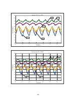
Страница 33: ...ta AT30䉝 Pull down Pull up Temperture 100 80 60 40 20 0 20 40 0 2 4 6 8 10 Time hour Temperature 䉝 230V50Hz䚷Pull down Pull up AT35䉝 Pull down Tempertures 120 100 80 60 40 20 0 20 40 60 0 2 4 6 8 10 Time hour Temperature 䉝 1 2䠤 H䚷EVA䚷OUT L EVA䚷IN L䚷EVA䚷OUT ...

Страница 34: ...1 5 2 2 5 3 3 5 4 0 2 4 6 8 10 Time hour Pressure MPa 㻴㼋㻼㼐㼇㻹㻼㼍㼉 㻴㼋㻼䡏㼇㻹㻼㼍㼉 㻸㼋㻼㼐㼇㻹㻼㼍㼉 㻸㼋㻼䡏㼇㻹㻼㼍㼉 AT35䉝䚷Pull down䚷Current Input 0 100 200 300 400 500 600 700 800 900 1000 0 1 2 3 4 5 6 7 Time hour Input W 0 1 2 3 4 5 6 7 8 9 10 W䚷䠄50Hz䠅 A䚷䠄50Hz䠅 Current A ...

Страница 35: ...per shelf 30mmD 69mm 69mm 10mmH 43mmW 10mmH 10mmH Middle area measuring points 6 9 10mm H upper from Middle shelf 30mm D away and 43mm W away from each corner 10 Center and 10mm H upper from Middle shelf Front Back Temperature uniformity 17points measuring 14 13 11 12 15 9 8 6 7 10 4 3 1 2 5 17 16 Left Right Bottom area measuring points 11 14 69mm H upper from Bottom of interior 30mm D away and 43...

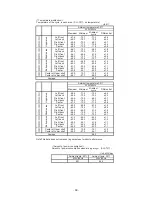
Страница 36: ...al 䐟 Left front 75 0 79 1 77 1 2 1 䐠 Left back 76 8 81 3 79 1 2 3 䐡 Right front 74 7 79 5 77 1 2 6 䐢 Right back 76 8 81 6 79 2 2 4 䐣 Center 77 1 82 2 79 7 2 4 䐤 Left front 77 7 80 0 78 9 1 2 䐥 Left back 79 5 82 2 80 9 1 4 䐦 Right front 77 4 79 7 78 6 0 9 䐧 Right back 79 3 82 1 80 7 1 2 䐨 Center 79 0 80 7 79 9 1 4 䐩 Left front 76 2 79 1 77 7 1 5 䐪 Left back 77 7 80 9 79 3 1 6 䐫 Right front 77 5 80 ...

Страница 37: ...k 66 9 73 9 70 4 3 5 䐡 Right front 65 6 72 9 69 3 3 7 䐢 Right back 68 0 76 5 72 3 4 3 䐣 Center 67 5 75 0 71 3 3 8 䐤 Left front 66 0 69 8 67 9 1 9 䐥 Left back 69 0 74 6 71 8 2 8 䐦 Right front 65 5 69 0 67 3 1 8 䐧 Right back 68 9 74 0 71 5 2 6 䐨 Center 68 2 72 3 70 3 2 1 䐩 Left front 61 3 63 5 62 4 1 1 䐪 Left back 63 4 66 4 64 9 1 5 䐫 Right front 60 5 62 7 61 6 1 1 䐬 Right back 61 1 64 4 62 8 1 7 䐭 ...

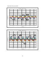
Страница 38: ...on Condition SV 80䉝 AT30䉝 90 88 86 84 82 80 78 76 74 72 70 0 0 0 5 1 0 1 5 2 0 2 5 3 0 Time hour Temperature 䉝 䐣 䐯 䐭 䐮 䐨 Condition SV 80䉝 AT20䉝 90 88 86 84 82 80 78 76 74 72 70 0 0 0 5 1 0 1 5 2 0 2 5 3 0 Time hour Temperature 䉝 䐣 䐭 䐯 䐮 䐨 ...

Страница 39: ...䉝 AT30䉝 80 78 76 74 72 70 68 66 64 62 60 0 0 0 5 1 0 1 5 2 0 2 5 3 0 Time hour Temperature 䉝 䐭 䐯 䐣 䐮 䐨 Condition SV 70䉝 AT20䉝 80 78 76 74 72 70 68 66 64 62 60 0 0 0 5 1 0 1 5 2 0 2 5 3 0 Time hour Temperature 䉝 䐭 䐯 䐣 䐨 䐮 ...

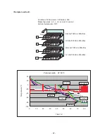
Страница 40: ...tles 4th shelf 500ml x 45bottles Front d c b a Conditions 500ml water x 180 bottles 䠄90L䠅 Measuring points a b c d L eva out H eva out Ambient temperature 30䉝 Pull down data AT 30䉝 100 80 60 40 20 0 20 40 0 10 20 30 40 50 60 70 80 Time䠄hr䠅 Temperature䠄䉝䠅 L eva out H eva out Load a Load b Load c Load d ...

Страница 41: ... 10 0 10 0 100 200 300 400 500 600 700 800 Time min Temperature 䉝 L eva out H eva out Load a Load b Load c Load d Pull up data AT30䉝 100 90 80 70 60 50 40 30 20 10 0 10 20 30 40 0 10 20 30 40 50 60 70 80 90 Temperature䠄䉝䠅 L eva out H䚷eva out Load a Load b Load c Load d Time hr ...

Отзывы: