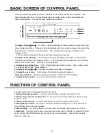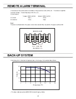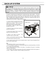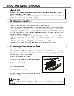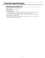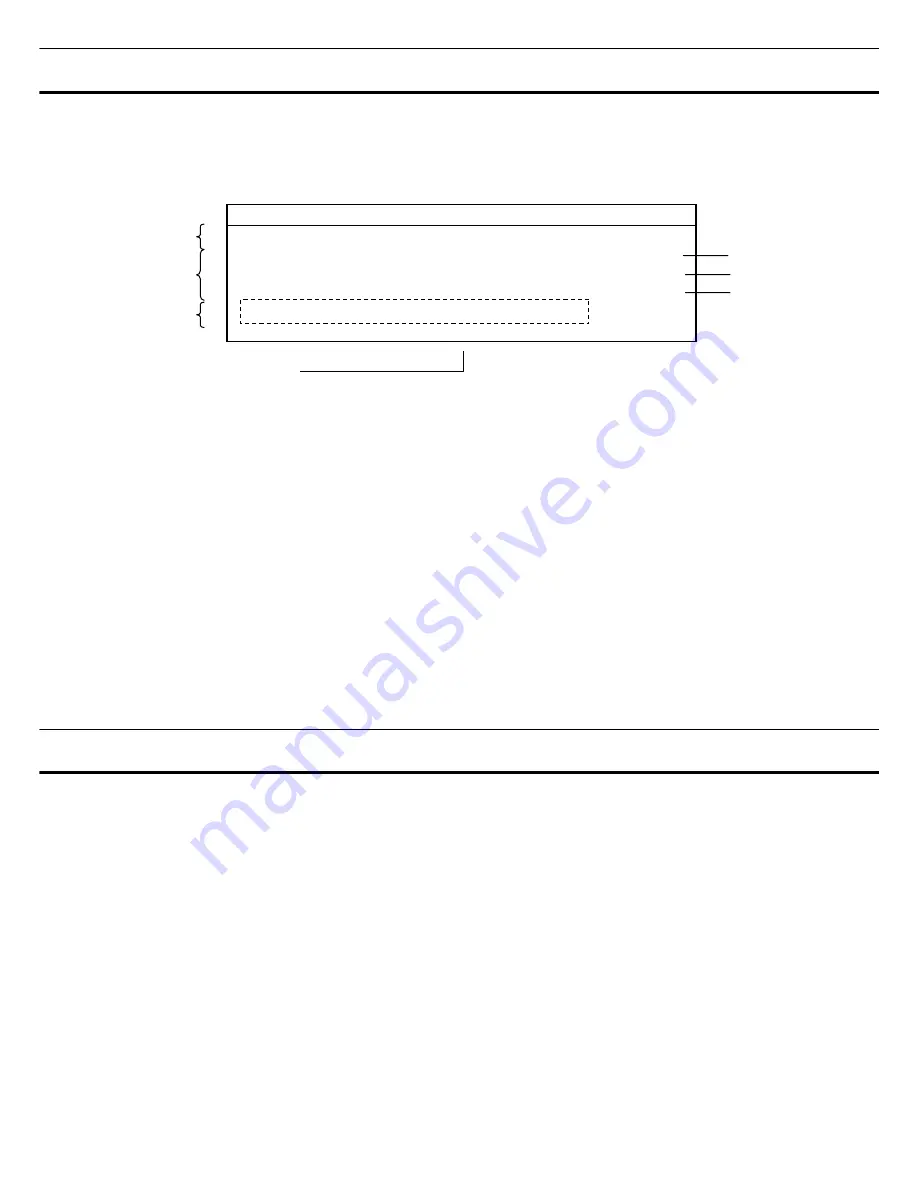
BASIC SCREEN OF CONTROL PANEL
When the power supply switch is turned on, the basic screen of the control panel is indicated. The
numerical value after "Temp" shows set temperature, and a big number under that shows present
chamber temperature. The bottom shows a present date and time.
1
4
5
7
0
1
0
2
1
1
1
2
1
3
1
4
1
5
1
6
1
7
1
8
1
9
2
0
2
1
2
2
2
3
2
4
2
5
2
6
2
7
2
8
2
9
3
0
3
1
3
2
3
3
3
4
3
5
3
6
3
7
3
8
3
9
4
0
1
T o p
S c r e e n
2
T e m p - 1 5 0
o
C
3
A l a r m
:
N o r m a l
4
S t a t u s
:
S t a n d - b y
5
D o o r
:
C l o s e d
6
2 0 0 6 / 0 7 / 0 1
1 2 : 0 0 : 0 0
−150
℃
6
2
3
1. Display of alarm
(
Alarm
)
:
An “Alarm” is indicated alternately in the reversal/non-reversal character
during the alarm operation. Warning is indicated alternately in the reversal/non-reversal character at the
time of warning. “Normal” is usually indicated. The complementary message is indicated in the
message column.
・
“Test” is indicated alternately at the alarm test by the reversal/non-reversal.
2. Display of status (Status):
The message of the indication (Status) of the status number and the
complement is indicated in the message column. An error message is indicated at the time of warning.
Refer to P.23 for the details. “Stand-by” is usually indicated.
3. Display of door status (Door):
“Door” is highlighted when the door is open. When a door is close,
it is indicated with "Closed". (usual character)
4. Display of setting
(
Temp
)
:
Set value of chamber temperature is displayed.
5. Display of current value:
Current value of chamber temperature is displayed.
6. Message indication:
Various messages are indicated. Refer to P.23 for the details.
7. Display of date and time:
The current date and time are displayed.
FUNCTION OF CONTROL PANEL
The following functions are available through control panel:
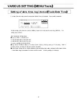
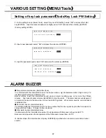
1. Setting of standby operation:
To set a running condition at the start-up.
(
refer to P.16
)
2.
Setting of log cycle and sending to PC:
To set a log cycle of running data and to send a running
log to PC.
(
P.18
)
3.
Setting of date and time:
To set the date and time shown on the basic screen.
(
P.21
)
4.
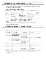
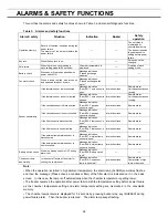
Setting/display of alarm:
High limit (or low limit) temperature setting
(
P.15
)
. Power failure alarm
(P.23) and filter alarm (P.23) are indicated.
5. Default setting:
To set the default for LCD panel and communication (DAQ) speed etc.
(
P.20
)
6. Alarm test:
The test of alarm buzzer, alarm lamp and remote alarm is effective by pressing the alarm
buzzer stop key (BUZZER) for about five seconds during normal operation. Pressing the key again
finishes the alarm test.
15

