background image

English

39

1

MENU CONFIGURATION AND OPERATIONS

This section describes the menu configuration and the 
menu items to be selected for each operation.

1

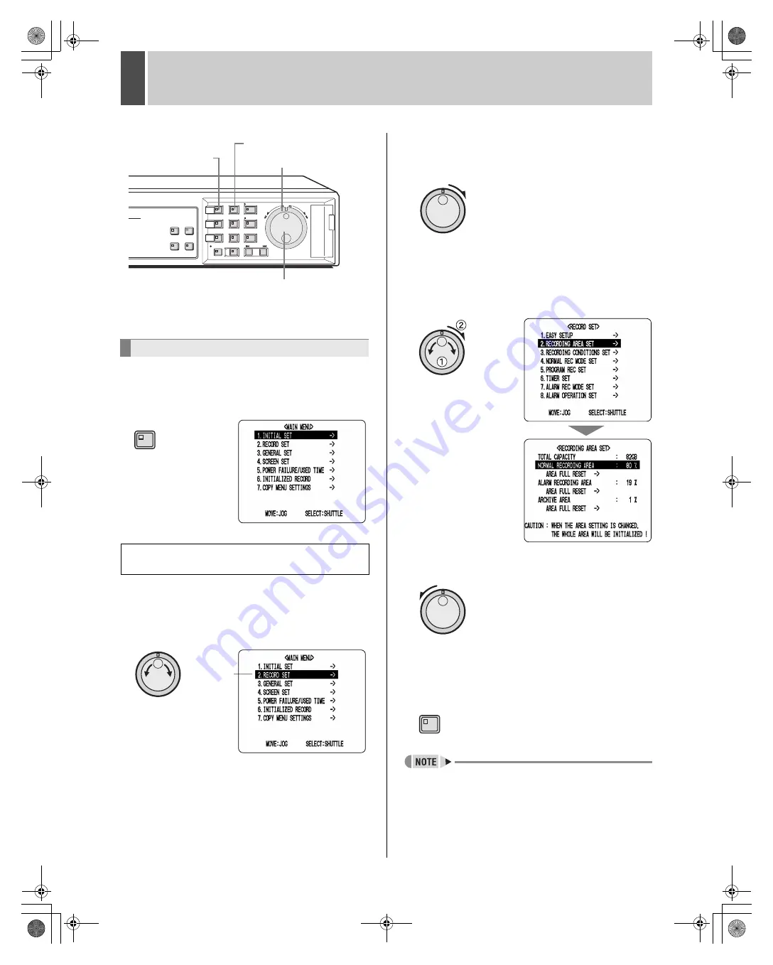
 Press the [MENU] button.

The MENU indicator lights up and the <MAIN MENU> is 
displayed.

2

Turn the jog dial to select a menu.

(Example: 2. RECORD SET)

When you move the cursor, the selected item is displayed 
in reverse.

3

Turn the shuttle dial clockwise.

The sub-menus appear.
The cursor is positioned on the first setting item.

4

Turn the jog dial to select a sub-menu, 
and then turn the shuttle dial clockwise.

The corresponding setting screen is displayed, and the 
cursor is positioned on the first item.

„

To return to the previous menu

Turn the shuttle dial counter-clockwise.

5

Press the [EXIT] button.

The setting procedure is ended and the display returns to 
the normal screen.

z

Menus can be opened even during the recording 
process.

z

Menu settings cannot be changed during the recording 
process. Accordingly, recording will have to be stopped 
in order to allow changes to be made.

Basic menu operations

Moving from the <MAIN MENU> to a sub-menu 
or setting screen

[EXIT] button

Jog dial

Shuttle dial

[MENU] button

MENU

Cursor 

position

EXIT

e00_l8hbe_us_7.book  Page 39  Friday, April 16, 2004  1:42 PM

Содержание DSR-3506

Страница 1: ...Spanish INSTRUCTION MANUAL z Utilisez le CD ROM fourni pour consulter le MANUEL D INSTRUCTIONS en français et en espagnol z Consulte en el CD ROM el MANUAL DE INSTRUCCIONES en francés y en español e00_l8hbe_us_7 book Page 1 Friday April 16 2004 1 42 PM ...

Страница 2: ...z Do not handle the power cord with wet hands z Do not pull on the power cord when disconnecting it from an AC wall outlet Grasp it by the plug z If any liquid is spilled on the unit unplug the power cord immediately and have the unit inspected at a factory authorised service centre z Do not place anything directly on top of this unit SERVICE This unit is a precision instruments and if treated wit...

Страница 3: ... the archive area z Searching for intruder motion using motion detection search Two level security lock function lets you restrict users for data and equipment management JP 79 Expandable can be connected to a PC z Recorded video can be copied to CompactFlash cards z A built in LAN terminal provides support for network control thus facilitating live monitoring playback searches and menu setting z ...

Страница 4: ...en 16 Viewing on multiple screens 16 Viewing with automatic screen selection 17 Viewing on the monitor 2 18 3 RECORDING 19 Normal recording 19 Timer recording 19 Alarm recording 20 Pre alarm recording 21 4 PLAYBACK 22 Playing video on a full screen 22 Fast forward and fast rewind playback 22 Changing the playback speed 22 Enlarging the playback video 23 Viewing still images 24 Performing frame adv...

Страница 5: ...8 Setting the motion sensors 72 Setting alarm operation and display 74 Canceling alarms 75 4 GENERAL SET 76 General settings 76 Setting data display 76 Setting display for video loss 77 Setting the buzzer 78 Setting the security lock 79 Setting and initializing the hard disk 81 Expanding the hard disk capacity 82 Network settings 82 5 SCREEN SET 86 Setting quad and multi 6 display 86 Setting the p...

Страница 6: ... impact or vibration It is recommended that you place the HDD on a soft level surface with the printed circuit board facing upward after it has been unpacked z Take care to avoid subjecting the HDD to sudden impact or vibration when removing and tightening screws as part of the HDD replacement procedure Tighten all screws securely to ensure that they do not loosen The HDD is sensitive to static el...

Страница 7: ... or any connected devices z As a precaution against malfunction or accidents it is advisable to periodically back up important recordings or to perform mirroring Protection of the hard disk The hard disk is checked automatically when the power is turned on If an abnormality is detected the POWER indicator will begin to flash If you need initialize the hard disk or to save images stored on it conta...

Страница 8: ...orresponding indicator lights up and the video feed from that camera is displayed on screen z During quad or multi 6 screen display The indicators corresponding to the cameras being displayed on the monitor are lit up z If video is lost The indicator starts to flash z If an alarm occurs The indicator for the corresponding camera starts to flash 7 QUAD button and indicator JP 16 The QUAD button is ...

Страница 9: ...constant speed of playback or slow playback The indicator lights up while the shuttle dial is locked When a password has been set furthermore this button can be pressed for at least three seconds to activate the security lock 20 REC STOP button and indicator JP 19 The REC STOP button is pressed to start normal recording and the indicator lights up during this process Furthermore pressing this butt...

Страница 10: ...LO CK SET IN CLOCK SETOUT NO N REC O UT W ARNIN G O UT FULL EXIT TIM ER IN NC 9 10 13 14 12 11 8 7 6 5 4 3 1 2 Pin Signal C Ground ALARM IN 1 Alarm input No 1 ALARM IN 2 Alarm input No 2 ALARM IN 3 Alarm input No 3 ALARM IN 4 Alarm input No 4 ALARM IN 5 Alarm input No 5 ALARM IN 6 Alarm input No 6 C Ground ALARM RESET Alarm reset input ALARM FULL Capacity warning output for alarm recording area sp...

Страница 11: ...ions AC IN LAN ALARM IN SENSOR ALARM OUT C 1 2 3 4 5 6 C C C C R1 R2 C 1 2 3 4 5 6 C MON2 MAIN MONITOR MIC IN OUT IN AUDIO ALL RESET 1 2 3 4 5 6 IN OUT VIDEO 02 01 04 03 ALARM OUT REMOTE ALARM FULL ALARM RESET CLO CK SET IN CLOCK SETOUT NO N REC O UT W ARNO R O UT FULL EXIT TIM ER IN NC Wrap the microphone cable twice around the supplied core clamp before attaching it Video input terminal PC Monit...

Страница 12: ...he hard disk In this type of situation initialize the hard disk JP 81 If you need to save video stored on the disk contact the dealer from whom you purchased this digital video recorder z The power cord s ground terminal is not provided for enhanced safety rather it can be used to reduce the level of interference when the digital video recorder is connected to analog devices If a large amount of n...

Страница 13: ... on the hard disk Set to EN Enhanced by default 6 Audio recording display A is displayed when audio is being recorded or played back 7 Alarm display and alarm count display JP 68 When you set an alarm using the ALARM REC MODE SET menu item the alarm display area presents the following information zWhen alarm recording is set ALARM is displayed ALARM is flashed during alarm recording zWhen pre alar...

Страница 14: ...ursor positioned on ENGLISH 4 Turn the shuttle dial clockwise and then turn the jog dial to select the desired language The set item flashes 5 When you have made a selection turn the shuttle dial clockwise The cursor moves to the date and time The language has now been set To return to the normal screen press the EXIT button Changing the position of the operation display area Changing the language...

Страница 15: ...e LANGUAGE LANGUE IDIOMA screen is displayed 4 Turn the shuttle dial clockwise 01 flashes indicating the month 5 Turn the jog dial to select 05 and then turn the shuttle dial clockwise 01 flashes indicating the day 6 Use the same procedure to set the day 22 year 2004 hour 08 and minute 30 When you have set the minute the cursor moves to MODE under DAYLIGHT SAVING and the clock starts counting from...

Страница 16: ...ing Manual When monitoring recording is performed in response to pressing of the REC STOP button Timer recording Automatic Recording is carried out in accordance with timer settings Recording mode Recording method Alarm recording Automatic Recording is carried out when alarm recording is set to ENABLED Specifically alarm images are recorded in the alarm recording area in response either to operati...

Страница 17: ...monitor display is divided in four Video from Camera No 1 through Camera No 4 is displayed each of the segments 2 To view video not currently being displayed press the QUAD button once again Each time this button is pressed the content of the split screen will toggle between video from cameras No 1 through No 4 and video from cameras No 5 No 6 No 1 and No 2 To return to full screen display press t...

Страница 18: ...y returns to the normal screen 1 Press the QUAD button The QUAD indicator lights up and the monitor display is divided in four 2 Press the SEQUENCE button The content of the split screen will automatically toggle between video from cameras No 1 through No 4 and video from cameras No 5 No 6 No 1 and No 2 3 Press the SEQUENCE button once again Automatic selection ends and normal quad screen display ...

Страница 19: ...tton The video displayed on the monitor 2 changes automatically based on camera numbers Press the SEQUENCE button once again to cancel automatic selection z If the monitor 2 is not synchronized with the connected cameras vertical picture instability may occur upon the switching of camera video 1 Set MON 2 DISPLAY from ALARM OPERATION SET to ON JP 74 When an alarm occurs the corresponding video is ...

Страница 20: ...le until a time has been set for the digital video recorder Make sure to set the time JP 43 1 Press the TIMER button The TIMER indicator lights up and the digital video recorder enters timer recording standby mode 1 See P 65 for more details on timer recording settings 2 At the time specified for the start of timer recording the REC STOP indicator lights up REC appears on screen i e the recording ...

Страница 21: ...er can be increased to 32 000 Note however since settings for each condition will affect the maximum number of recordings that can be made be sure to check menu settings and display content 3 End alarm recording When the alarm duration has expired default setting 20 seconds both REC and ALARM finish flashing from the operation display and recording stops z When the space remaining in the alarm rec...

Страница 22: ...ding for the first time the default settings are used For details regarding modification of the picture quality or recording rate see P 62 z When the space remaining in the alarm recording area drops below a preset value the FULL indicator on the digital video recorder s front panel starts to flash If recording is continued beyond this point the alarm recording area will become full recording will...

Страница 23: ...ial clockwise or counter clockwise during video playback When turned clockwise the symbol appears in the operation display area and fast forward playback is started When turned counter clockwise the symbol appears in the operation display area and fast rewind playback is started Normal playback is resumed when you release the shuttle dial z If the SHUTTLE HOLD button is pressed while the shuttle d...

Страница 24: ... Returning to normal playback Press the SHUTTLE HOLD button to turn off SHUTTLE HOLD indicator Turn the shuttle dial either clockwise or counter clockwise to display in the operation display area Normal video playback is restored 1 Press the ZOOM button during playback Zoom indicator lights and a blue zoom frame appears in the center of the screen 2 Move the zoom frame to the area to be magnified ...

Страница 25: ... Turn the jog dial clockwise or counter clockwise while playback is paused Clockwise The still image is moved forward by one frame or field Counter clockwise The still image is moved back by one frame or field z The jog dial can be turned to increase the speed of frame advance z When the images from normal recording area and alarm recording area are played back in succession the quality of the pic...

Страница 26: ...eo from cameras No 5 No 6 No 1 and No 2 Returning to full screen display Press the appropriate CAMERA SELECT button 1 Press the MULTI button during playback The MULTI indicator lights up and the monitor display is divided in six Returning to full screen display Press the appropriate CAMERA SELECT button z In the case of both quad and multi 6 screen display you can change the position in which play...

Страница 27: ...layback alarm video from the recording list 2 ALARM THUMBNAIL SEARCH JP 28 Lets you search and playback alarm video using a thumbnail list 3 TIME DATE SEARCH JP 28 Lets you search and playback recorded video based on date and time 4 ARCHIVE AREA SEARCH JP 30 Lets you playback video that has been stored in the archive area 5 MOTION DETECTION SEARCH JP 30 Lets you search and playback video of moving...

Страница 28: ...the cursor and select the video for playback A preview of the selected alarm video is displayed in the preview screen In this case the video from the instant of alarm occurrence is displayed z To display the next or previous recording Turn the jog dial clockwise or counter clockwise accordingly z To leave search mode Press the SEARCH button SEARCH indicator turns off 4 Turn the shuttle dial clockw...

Страница 29: ...for playback The alarm number for the selected recording will start to flash z To display the next or previous recording Turn the jog dial clockwise or counter clockwise accordingly z To leave search mode Press the SEARCH button SEARCH indicator turns off 4 Turn the shuttle dial clockwise The selected recording is played back in full screen mode z In the same way as for alarm searching playback is...

Страница 30: ...rn the jog dial to select 04 year 5 Turn the shuttle dial clockwise and then turn the jog dial to select 20 hour 6 Turn the shuttle dial clockwise turn the jog dial to change to 00 minutes and then turn the shuttle dial clockwise once again The cursor moves to PREVIEW 4 Turn the shuttle dial clockwise After searching the recording for the date and time settings is displayed in the preview screen z...

Страница 31: ...r playback The selected image is displayed on the preview screen z To display the next or previous recording Turn the jog dial clockwise or counter clockwise accordingly z Up to eight recordings can be displayed in the ARCHIVE AREA SEARCH screen z To leave search mode Press the SEARCH button SEARCH indicator turns off 5 Turn the shuttle dial clockwise The selected recording is played back on the f...

Страница 32: ...to START PREVIEW 7 Turn the shuttle dial clockwise The screen changes and the preview screen for Camera No 4 appears 1 START Indicates the date and time of recording of the first image in the selected recording area s 2 END Indicates the date and time of recording of the final image in the selected recording area s 3 MOTION SENSOR Indicates the motion sensor setting 4 PREVIEW Displays the selected...

Страница 33: ...rn the jog dial clockwise or counter clockwise to move the cursor to the position where a sensor is to be set 2 Turn the shuttle dial clockwise to set a motion sensor ON OFF 3 Use the jog dial in the same way to set sensors at other locations z All sensors on the same line as the cursor can be turned on simultaneously by pressing the MENU RESET button 3 Turn the jog dial to move the cursor to LEVE...

Страница 34: ...o select VIEW and then turn the shuttle dial clockwise Normal playback will be started for the specified recording z By specifying a camera number or channel and performing MOTION DETECTION SEARCH playback can be carried out for only the specified camera number In such a case the title information date information and or time information may partially disappear z To playback a recording from a dif...

Страница 35: ...ng area or alarm recording area to a CompactFlash card it is temporarily stored in the archive area before being copied from there to the CompactFlash card Note however that this video will not be retained in the archive area z If archive area becomes full copy important video to a CompactFlash card JP 36 Following this delete unwanted video using AREA FULL RESET for the archive area from 2 RECORD...

Страница 36: ...al clockwise ARCHIVE AREA starts to flash Settings indicates the default setting 5 Turn the jog dial to select ARCHIVE AREA and then turn the shuttle dial clockwise The cursor moves to HOW MANY 6 Turn the shuttle dial clockwise and then turn the jog dial to set HOW MANY to 10 Any value between 1 and 60 can be set 7 Turn the shuttle dial clockwise PICTURES flashes Copying video to the hard disk s a...

Страница 37: ...B 1 Insert a CompactFlash card Insertion method Removal method Setting Description PICTURES The specified number of images after the specified location will be copied SECONDS The specified duration in seconds after the specified location will be copied MINUTES The specified duration in minutes after the specified location will be copied Copying normal recording area alarm recording area or archive...

Страница 38: ...p to 40 000 images can be copied in a single operation When specifying the number of images using MINUTES copying will end at the point at which 40 000 images are copied z Alarm recordings can only be copied one event at a time 8 Turn the shuttle dial clockwise The cursor moves to START 9 Turn the shuttle dial clockwise 1 Copying to the CompactFlash card starts The message COPY TO COMPACT FLASH is...

Страница 39: ...ur PC open the file INDEX HTM found in each date folder using a browser i e Internet Explorer 5 0 or later You will then be able to view the JPEG images individually or in slide show format etc z Playing video with audio that has been copied to a CompactFlash card video with audio can be played using DVR Viewer For more details refer to the Manual for Remote Operation by Network Connection z JPEG ...

Страница 40: ...en turn the shuttle dial clockwise The corresponding setting screen is displayed and the cursor is positioned on the first item To return to the previous menu Turn the shuttle dial counter clockwise 5 Press the EXIT button The setting procedure is ended and the display returns to the normal screen z Menus can be opened even during the recording process z Menu settings cannot be changed during the ...

Страница 41: ...e items to be returned to default settings 2 Press the MENU RESET button The displayed settings are restored to their default values Movement and confirmation in sub menus and setting screens 1 To move the cursor up or down Turn the jog dial 2 To move the cursor right or to confirm an item Turn the shuttle dial clockwise 3 To change a setting value Turn the jog dial Restoring menu setting items to...

Страница 42: ...ting is to be performed by deleting old video or recording is to be stopped when any of the hard disk s recording areas become full 4 NORMAL REC MODE SET JP 62 Sets the recording quality audio recording the recording rate and program recording 5 PROGRAM REC SET JP 63 Sets program recording for cameras and the program recording rate 6 TIMER SET JP 65 Makes timer settings so that operations can be s...

Страница 43: ...l 01 through channel 06 on and off and sets time synchronization 4 COLOR LEVEL JP 92 Adjusts the color of video displayed on monitors 5 POWER FAILURE USED TIME This sub menu is used to confirm the date and time of power failures and the amount of hard disk usage JP 94 Provides a display of the date and time of power failures and the amount of hard disk usage 6 INITIALIZED RECORD This sub menu is u...

Страница 44: ... the monitor Set the date and time displayed on the normal screen and daylight saving Aligns the time of all digital video recorders in situations where multiple recorders are connected P 13 P 43 2 CAMERA DETECT Automatically detects cameras that have been connected P 46 3 TITLE SET Sets a unique title for each camera so that these can be displayed on screen P 47 4 HOLIDAY SET Sets specific dates ...

Страница 45: ...display reaches April 4 2004 01 59 the next clock display is 03 00 putting the clock an hour ahead After the clock display reaches October 31 2004 01 59 the next clock display is 01 00 putting the clock an hour behind back to standard time 1 Sets the week for switching to daylight saving 2 Sets the day of the week 3 Sets the month 4 Sets the time 5 Sets the week for ending daylight saving 6 Sets t...

Страница 46: ...are connected Default setting 01 00 At the set time all connected recorders will be aligned to the same time to a precision of seconds 1 Connect the CLOCK SET OUT terminal on the rear of the first digital video recorder to the CLOCK SET IN of the second recorder 2 Press the MENU button The MENU indicator lights up and the MAIN MENU is displayed 3 Turn the jog dial to select 1 INITIAL SET and then ...

Страница 47: ...value is 01 00 z Only an hour value can be set using ADJUST TIME It is not possible to set a value for minutes and seconds Use the following procedure to automatically detect cameras that have been connected An OFF setting should be made for cameras that have not been connected 1 Press the MENU button The MENU indicator lights up and the MAIN MENU is displayed 2 Turn the jog dial to select 1 INITI...

Страница 48: ...the MENU button The MENU indicator lights up and the MAIN MENU is displayed 2 Turn the jog dial to select 1 INITIAL SET and then turn the shuttle dial clockwise The INITIAL SET screen is displayed 3 Turn the jog dial to select 3 TITLE SET and then turn the shuttle dial clockwise The normal monitoring screen is displayed with a title setting field in the center 4 Press the No 3 CAMERA SELECT button...

Страница 49: ...1 camera No Use the following procedure to set specific dates as holidays to have the operation for Sunday used on those days also Dates such as national holidays and company off days should be set as holidays when you want those dates to have the same security as Sundays Setting conditions Be sure to always switch SET to ON after completing timer settings for Sunday i e SUN JP 65 Example Setting ...

Страница 50: ... to 17 5 Turn the shuttle dial clockwise after setting The cursor moves to 2 6 Use the same procedure to set other holidays 7 Press the EXIT button The setting procedure is ended and the display returns to the normal screen The default setting is all z If DLY is set using timer settings timer recording on the above mentioned holidays will also be carried out in accordance with daily settings In ot...

Страница 51: ...t to morning 20 00 to 6 00 Cameras No 1 3 and 4 automatic selection is carried out The following menu settings must be made to enable operation of the time periods After completing these settings be sure to then carry out timer setting Setting automatic selection of camera video Set which automatically selected camera to display video from and the switching interval To do this set SEQUENCE SET fro...

Страница 52: ...n the jog dial to select 5 TIME PERIOD SET and then turn the shuttle dial clockwise The TIME PERIOD SET screen is displayed 4 Turn the jog dial to select TIME PERIOD A and then turn the shuttle dial clockwise 00 from T1 flashes indicating the hour 5 Turn the jog dial to set T1 hours to 06 hours and then turn the shuttle dial clockwise 00 from T1 flashes indicating the minutes 6 Turn the jog dial t...

Страница 53: ...nored and T1 operates from midnight to midnight Example 2 Setting time period operation as follows Automatic selection and monitor masking for TIME PERIOD A Motion sensing for TIME PERIOD B 1 Turn the jog dial to move the cursor to SEQUENCE within SELECT TIME PERIOD and then turn the shuttle dial clockwise TIME PERIOD A flashes 2 Turn the jog dial to select TIME PERIOD A or TIME PERIOD B and then ...

Страница 54: ...ings based on a number of days or a rate P 53 2 RECORDING AREA SET Displays the total capacity of the hard disk Sets the normal recording area the alarm recording area and the archive area P 57 3 RECORDING CONDITIONS SET Sets whether overwriting is to be performed by deleting old video or recording is to be stopped when any of the hard disk s recording areas become full Also sets the auto delete P...

Страница 55: ...is displayed 3 Turn the jog dial to select 1 EASY SETUP and then turn the shuttle dial clockwise The EASY SETUP screen is displayed 4 Turn the jog dial to select RECORDING DURATION BASE and then turn the shuttle dial clockwise The RECORDING DURATION BASE screen is displayed with the cursor positioned on RECORDING DURATION The number of detected cameras is indicated by NUMBER OF CAMERAS z Confirm t...

Страница 56: ...s indicates the default setting 10Set AUDIO RECORDING Example ON Settings indicates the default setting z Audio recording can only be specified when the recording rate is 1 00 FPS or greater z When set to ON the letter A indicating that audio will be recorded is displayed in front of recording rate As both video and audio will be stored in the normal recording area this area s overall capacity wil...

Страница 57: ...ursor positioned on REC RATE The number of detected cameras is indicated by NUMBER OF CAMERAS z Confirm that the number of cameras connected to the digital video recorder is the same as the number of displayed recording cameras If this is not the case check the wiring between cameras and the digital video recorder and then carry out CAMERA DETECT JP 46 5 Turn the shuttle dial clockwise 60 00 flash...

Страница 58: ... If a valid figure cannot be calculated ERROR will be displayed z When simple recording settings and individual settings are both set the most recent settings override previous settings z Easy setup settings cannot be used with program recording or day specific timer recording Use the following procedures to confirm the hard disk s total recording capacity and also the allocation for each recordin...

Страница 59: ... normal recording area As video will only be recorded to the alarm recording area in this type of case the area allocations should be reviewed and set accordingly z If the normal recording area is set to 0 the PLAY STOP button will be deactivated In such a case search playback should be carried out z A maximum of 16 000 alarm recordings can be made on one hard disk If hard disk expansion is carrie...

Страница 60: ... will not be adopted 7 Turn the shuttle dial clockwise 1 The hard disk is initialized 2 The RECORDING AREA SET screen appears and the modified recording capacities are adopted 8 Press the EXIT button The setting procedure is ended and the display returns to the normal screen By default when all of the space in the hard disk s normal recording area and alarm recording area has been used up repetiti...

Страница 61: ...DING AREA from RECORDING CONDITIONS SET screen to ON JP 60 z Whenever AREA FULL RESET is performed for NORMAL RECORDING AREA or ALARM RECORDING AREA the video recorded in the corresponding area will be overwritten z Images in the archive area are erased when AREA FULL RESET is performed for the archive area Use the following setting procedure to indicate whether overwriting is to be performed dele...

Страница 62: ...hen the remaining capacity for any recording area reaches the specified percentage value In addition the FULL indicator for the normal recording area or the ALARM FULL indicator for the alarm recording area will flash at this time You can set a storage period for recorded data as described below When the set period has expired the corresponding data will be automatically deleted 1 Turn the jog dia...

Страница 63: ...EC MODE SET screen is displayed 4 Turn the shuttle dial clockwise ENHANCED flashes indicating enhanced quality recording 5 Turn the jog dial to select PICTURE QUALITY and then turn the shuttle dial clockwise Settings indicates the default setting z The file size is intended as a general guideline and actual sizes will depend on the recorded video The following settings are carried out using the sh...

Страница 64: ...rams No 1 through No 4 can be setup for this purpose For example Program No 1 could be setup to record from cameras No 1 through No 4 only whereas Program No 2 could be setup to record from cameras No 3 through No 6 In addition these programs can also be used for timer recording z Even if audio recording is set to ON using the NORMAL REC MODE SET screen certain settings for program recording may m...

Страница 65: ...ra No 1 is now set to record at a rate of 3 75 The cursor moves to 02 Valid recording rates 30 15 7 5 3 75 1 875 1 0 0 500 0 330 0 250 0 200 0 100 0 050 0 033 Unit FPS A selection cannot be made when pre alarm recording has been set to ON 7 Set recording rates for Camera No 2 and Camera No 3 in the same way 8 With the cursor flashing on 04 camera number turn the jog dial to select OFF and then tur...

Страница 66: ...en using program recording 6 SET When set to ON timer recording is enabled When set to OFF timer recording is disabled 7 Settings for timer recording of over 24 hours Use these lines for timer recording spanning more than 24 hours z The settings made using NORMAL REC MODE SET are used to set quality and audio recording for timer recording JP 62 z Ensure that start and end times are input using 24 ...

Страница 67: ...t as holidays the operation for Sunday will be used on those days also JP 48 z If timer settings overlap recording is performed in the following sequence Each daily reservation DLY EXT Priority high low z If a reservation for a particular day overlaps with a daily reservation priority is given to that with the earliest start time If both have the same start time priority is given to that with the ...

Страница 68: ...turn the shuttle dial clockwise 5 Turn the jog dial to set OFF to ON 5 Press the EXIT button The setting procedure is ended and the display returns to the normal screen Use the following procedure to control the start and end of recording in response to signals received via the EXT TIMER ON terminal on the rear of the digital video recorder Example Recording at a rate of 5 FPS using the EXT TIMER ...

Страница 69: ...ial clockwise The ALARM REC MODE SET screen is displayed 3 Turn the shuttle dial clockwise OFF flashes 4 Turn the jog dial to select ALARM RECORDING and then turn the shuttle dial clockwise Settings indicates the default setting OLY AL RC ON TMR can be validated simply by making a timer setting Accordingly there is no need to press the TIMER button The following settings are carried out using the ...

Страница 70: ... Default setting for recording rate 15 00 FPS Default setting for duration 20 SEC Settings Operates while an alarm is being triggered 5 sec minimum Setting Description BASIC BA 15 kB NORMAL NO 22 kB ENHANCED EN 30 kB FINE FI 42 kB SUPER FINE SF 50 kB Setting Description OFF Audio recording is not carried out ON Audio recording is carried out Maximum number of alarm recordings Setting Description S...

Страница 71: ...OFF flashes 2 Turn the jog dial to change OFF to ON and then turn the shuttle dial clockwise A message appears indicating automatic rate adjustment NO flashes Settings indicates the default setting 3 Turn the jog dial to select YES for warning message and then turn the shuttle dial clockwise The cursor moves to recording rate and duration 4 Turn the shuttle dial clockwise REC RATE for PRE ALARM RE...

Страница 72: ...uttle dial clockwise ALARM flashes in the alarm trigger field 2 Turn the jog dial to select an alarm detection method and then turn the shuttle dial clockwise Settings indicates the default setting Setting conditions z When sensor selection has been made i e SENSOR ALARM AND SENSOR or ALARM OR SENSOR it will be necessary to set the motion sensors When pre alarm recording settings have been complet...

Страница 73: ... to NAMES AND FUNCTIONS OF PARTS for more details regarding operation of the jog dial and shuttle dial JP 8 1 Make timer settings for TIME PERIOD A and TIME PERIOD B from TIME PERIOD SET JP 50 2 Turn the jog dial select MOTION SENSOR and then turn the shuttle dial clockwise The motion sensor screen is displayed 3 Press the CAMERA SELECT button Select the camera for which motion sensors are to be s...

Страница 74: ... OFF Motion sensing is not carried out 1 to10 Motion sensing is carried out Lower values correspond to higher sensitivities Setting Description A The motion sensor alarm is triggered when a moving object is detected in A B The motion sensor alarm is triggered when a moving object is detected in B A AND B The motion sensor alarm is triggered when a moving object is detected by a sensor in both A an...

Страница 75: ... shuttle dial The RECORD SET screen is displayed 2 Turn the jog dial to select 8 ALARM OPERATION SET and then turn the shuttle dial clockwise The ALARM OPERATION SET screen is displayed with the cursor positioned on ALARM RETRIGGER 3 Turn the shuttle dial clockwise OFF flashes in the alarm trigger field 4 Turn the jog dial to set the alarm trigger to ON and then turn the shuttle dial clockwise The...

Страница 76: ...arm and hold it for approximately 3 seconds Alternatively connect a switch between the alarm reset terminal and C the grounded terminal and turn on the switch to cancel any alarm that is occurring Setting alarm display Setting Description FULL When an alarm is detected the video on the channel containing the alarm is displayed in full screen format on the main monitor 6 When an alarm is detected a...

Страница 77: ... to remove the date from the operation display area Main menu EXIT button Jog dial MENU button Shuttle dial General settings Setting Description Ref 1 DISPLAY SET Switches display items such as date and time from the operation display area Settings can also be made for situations where video signals are lost P 76 P 77 2 BUZZER SET Turns the buzzer on or off P 78 3 SECURITY LOCK SET Lets you set pa...

Страница 78: ... alarm count and type are not displayed When turned ACTIVE The operation display area changes as follows z ALARM is displayed when alarm video is recorded or played back z PRE is displayed when pre alarm video is recorded or played back z ARCHIV is displayed for playback from the archive area 6 Press the EXIT button The setting procedure is ended and the display returns to the normal screen z A ma...

Страница 79: ...f a button is pressed while the security lock is on Specifically the buzzer sounds twice with an interval of approximately 0 5 seconds 5 KEY IN default setting OFF Sounds the buzzer when a button is pressed 6 VIDEO LOSS default setting OFF A buzzer is sounded upon signal loss 3 Turn the shuttle dial clockwise OFF flashes for ALARM 4 Turn the jog dial to display ON and then turn the shuttle dial cl...

Страница 80: ...dial clockwise The first password character flashes 4 Turn the jog dial to select a character 0 to 9 A to Z Example Turn the jog dial to select 1 5 Turn the shuttle dial clockwise The second password character flashes 6 Use the same procedure to set 123456AB Setting the security lock Typical setting Operation LEVEL PASSWORD 4 8 USE ADMIN 123456AB ON USER AB123456 ON REC CONTROL ADMIN All operation...

Страница 81: ...o move the cursor to USER 2 Turn the shuttle dial clockwise The first password entry bar flashes Turn the jog dial to display A 3 Turn the jog dial clockwise The second password entry bar flashes Turn the jog dial to display B Use the same procedure as for the administrator password to set 123456 4 Following this turn the shuttle dial clockwise The cursor moves to OFF flashing 5 Turn the jog dial ...

Страница 82: ...e display returns to the normal screen z If an administrator password was entered the security lock is cancelled and the indicator is turned off z If a user password was entered the security lock is partially cancelled and the indicator remains lit This section describes how to initialize and expand the hard disk When a single hard disk is installed the hard disk capacity is displayed for DISK 1 w...

Страница 83: ...irroring has been set the recording rate is controlled automatically i e set to half of the normal value and the appropriate care must be taken z PLAYBACK DRIVE This parameter is used together with MIRRORING and it indicates which of the two hard disks is to be used to provide recordings for playback z If a playback problem occurs while mirroring is turned on change the hard disk used for playback...

Страница 84: ...net MENU Item Setting Description NETWORK CONTROL OFF The digital video recorder cannot be controlled via a network ON NETWORK ID 1 2 3 Connection condition on DVR Connection possible when not performing playback incl during copy or menu display Priority is given to operations on the PC When playback is being performed on the PC live video is displayed on the monitor connected to the digital video...

Страница 85: ... the digital video recorder to a network check the following settings with the network administrator z IP ADDRESS z SUBNET MASK z GATEWAY z PORT Three access levels are setup for network connection and a password is set for each Passwords comprise between 4 and 8 alphanumeric characters z ID or PASSWORD 4 8 at the top of the screen is the screen title You cannot move the cursor to this item Exampl...

Страница 86: ...en turn the shuttle dial clockwise 3 The third entry item 1 flashes Repeat the same procedure to set AB123456 4 Following this turn the shuttle dial clockwise 5 Where necessary use the same procedure to set the ID2 and ID3 passwords 6 When setting has been completed press the EXIT button The setting procedure is ended and the display returns to the normal screen EXIT e00_l8hbe_us_7 book Page 85 Fr...

Страница 87: ...clockwise NORMAL flashes for 1 MULTI SCREEN 3 Turn the jog dial to select CHANGE and then turn the shuttle dial clockwise The cursor moves to QUAD POSITION SET Settings indicates the default setting 4 Turn the shuttle dial clockwise The QUAD POSITION SET MENU screen is displayed with the cursor positioned on 01 Main Menu EXIT button Jog dial MENU button Shuttle dial Setting quad and multi 6 displa...

Страница 88: ...for multi 6 display 1 Turn the jog dial to select 1 MULTI SCREEN and then turn the shuttle dial clockwise NORMAL flashes 2 Turn the jog dial to select CHANGE and then turn the shuttle dial clockwise The cursor moves to QUAD POSITION SET Settings indicates the default setting 3 Turn the jog dial to select MULTI 6 POSITION SET and then turn the shuttle dial clockwise The MULTI 6 POSITION SET MENU sc...

Страница 89: ...ll screen and quad display Example Automatic switching of a full screen every 5 seconds 1 Press the MENU button and turn the jog dial to select 4 SCREEN SET and then turn the shuttle dial clockwise The SCREEN SET screen is displayed The cursor moves to 1 MULTI SCREEN 2 Turn the jog dial to move the cursor to FULL or QUAD from 2 SEQUENCE SET and then turn the shuttle dial clockwise 1S flashes for F...

Страница 90: ...B from TIME PERIOD SET JP 50 Specify TIME PERIOD A and TIME PERIOD B 2 Press the MENU button and turn the jog dial to select 4 SCREEN SET and then turn the shuttle dial clockwise The SCREEN SET screen is displayed The cursor moves to 1 MULTI SCREEN 3 Turn the jog dial to move the cursor to MAIN MON 2 MONITOR SET and then turn the shuttle dial clockwise The MAIN MON 2 MONITOR SET screen is displaye...

Страница 91: ...ise ON flashes 8 Turn the jog dial to select ON or OFF and then turn the shuttle dial clockwise After confirming this setting the cursor moves one position to the right 9 Use the same procedure to set the remaining channels 10Press the EXIT button The setting procedure is ended and the display returns to the normal screen z When setting a number of time periods together use the jog dial to move th...

Страница 92: ... SET screen is displayed The cursor moves to 1 MULTI SCREEN 3 Turn the jog dial to move the cursor to MASK and then turn the shuttle dial clockwise OFF flashes 4 Turn the jog dial to select ON and then turn the shuttle dial clockwise The cursor moves to MASK SET 5 Turn the shuttle dial clockwise The MASK SET screen is displayed 6 Turn the shuttle dial clockwise T 1 starts to flash for TIME PERIOD ...

Страница 93: ...gether use the jog dial to move the cursor to the next period after completing step 10 and repeat the process step 6 through 10 z The time period for T 1 through T 4 changes to that of TIME PERIOD A or TIME PERIOD B on P 50 z Network mask settings are valid only for the user connecting to the network with ID1 Users connecting using ID2 and ID3 will be able to display all channels Use the following...

Страница 94: ...wise AUTO Camera levels are adjusted automatically Default value 1 to 10 Manual adjustment to one of 10 levels Light 1 to Dark 10 Settings indicates the default setting 5 Press the EXIT button The setting procedure is ended and the display returns to the normal screen Setting Description AUTO Camera levels are adjusted automatically 1 to10 Manual adjustment to one of 10 levels Light 1 to Dark 10 E...

Страница 95: ...in sequence for the four most recent power failures i e the date and time of failure and recovery The number on the left is the number of power failures Example 028 For all numbers above 999 the number 999 is displayed 2 DISK1 USE Displays the total amount of operation time for disk 1 3 DISK2 USE Displays the total amount of operation time for disk 2 When only one hard disk is installed is display...

Страница 96: ...D screen is displayed 1 DATE TIME Displays the date and time of the operation 2 AREA Displays the area on which the operation was performed 3 Operation class Displays the operation performed as either of the following zINITIALIZED zAREA RESET z INITIALIZED is displayed when recording areas have been changed 2 Press the EXIT button The display returns to the normal screen Main menu EXIT button Jog ...

Страница 97: ...TTINGS screen is displayed 1 SAVE MENUS TO CF This saves the menu settings to a CompactFlash card 2 LOAD MENUS FROM CF This loads menu settings into the digital video recorder from a CompactFlash card Insert a CompactFlash card into the CompactFlash card slot 1 Turn the jog dial to select SAVE MENUS TO CF and then turn the shuttle dial clockwise WARNING screen is displayed 2 Turn the jog dial to s...

Страница 98: ...n the jog dial to select LOAD MENUS FROM CF and then turn the shuttle dial clockwise WARNING screen is displayed 2 Turn the jog dial to select YES and then turn the shuttle dial clockwise 1 The loading process begins 2 When this has been completed SYSTEM INITIALIZING is displayed and the display returns to the normal screen Use the following procedure to copy recording area settings 1 Turn the jog...

Страница 99: ...le dial clockwise The loading process starts When this has been completed SYSTEM INITIALIZING is displayed and the display returns to the normal screen z Normally COPY RECORDING AREA SETTINGS should be set to NO If set to YES hard disk initialization will be carried out and all recorded data will be lost e00_l8hbe_us_7 book Page 98 Friday April 16 2004 1 42 PM ...

Страница 100: ...5 Ω BNC x1 Audio input terminal 8 dBs 27 kΩ unbalanced RCA x1 Audio output terminal 8 dBs 600 Ω unbalanced RCA x1 Microphone input terminal 60 dBs 10 kΩ unbalanced 3 5 mm pin jack x1 CompactFlash card slot CompactFlash Type 2 front panel x1 Terminals LAN terminal 10BASE T 100BASE TX RJ 45 x1 Remote control input terminal Two wire voltage control x2 Alarm input terminals No volt contacts with a pul...

Страница 101: ...SPECIFICATIONS 100 English OTHER Units mm Dimensions 364 5 349 420 96 e00_l8hbe_us_7 book Page 100 Friday April 16 2004 1 42 PM ...

Страница 102: ... 293H 220H 160H 135H 2 73 456H 323H 242H 176H 149H 2 31 539H 382H 286H 208H 176H 2 00 622H 440H 330H 240H 203H 1 67 746H 529H 396H 288H 244H 1 43 871H 617H 462H 336H 284H 1 25 995H 705H 529H 384H 325H 1 11 1120H 793H 595H 432H 366H 1 00 1244H 881H 661H 480H 406H 0 50 2489H 1763H 1322H 961H 813H 0 33 3734H 2645H 1983H 1442H 1220H 0 25 4978H 3526H 2645H 1923H 1627H 0 20 6223H 4408H 3306H 2404H 2034H...

Страница 103: ...362H 307H 4 29 1095H 776H 582H 423H 358H 3 75 1252H 886H 665H 483H 409H 3 33 1408H 997H 748H 544H 460H 3 00 1565H 1108H 831H 604H 511H 2 73 1721H 1219H 914H 665H 562H 2 31 2034H 1441H 1080H 786H 665H 2 00 2347H 1663H 1247H 907H 767H 1 67 2817H 1995H 1496H 1088H 921H 1 43 3286H 2328H 1746H 1269H 1074H 1 25 3756H 2660H 1995H 1451H 1228H 1 11 4226H 2993H 2245H 1632H 1381H 1 00 4695H 3326H 2494H 1814H...

Страница 104: ... 00 11 3 00 12 3 00 12 2 73 12 2 73 13 2 73 13 2 31 13 2 31 14 2 31 14 2 00 14 2 00 15 2 00 15 1 67 15 1 67 16 1 67 16 1 43 16 1 43 17 1 43 17 1 25 17 1 25 18 1 25 18 1 11 18 1 11 19 1 11 19 1 00 19 1 00 20 1 00 20 0 50 21 0 50 21 0 33 22 0 33 22 0 25 23 0 25 23 0 20 24 0 20 24 0 10 25 0 10 25 0 05 26 0 05 26 0 03 27 0 03 Display sequence Recording rate FPS field sec 1 Note1 30 2 15 3 7 5 4 3 75 5...

Страница 105: ... available for the selected duration For example if the alarm duration is set to 3 seconds only 30 00 FPS will be selectable for the recording rate When setting fast recording rates it may be necessary to first of all change the alarm duration setting Table of pre alarm recording times Recording rate FPS field sec Recording time Display of time on menu screens s seconds m minutes 3s 3s 5s 5s 10s 1...

Страница 106: ...OD SET P 50 RECORD SET P 53 EASY SETUP P 53 RECORDING AREA SET P 57 RECORDING CONDITIONS SET P 60 NORMAL REC MODE SET P 62 PROGRAM REC SET P 63 TIMER SET P 65 ALARM REC MODE SET P 68 ALARM OPERATION SET P 74 RECORDING DURATION BASE P 54 REC RATE BASE P 56 MOTION SENSOR SET P 72 e00_l8hbe_us_7 book Page 105 Friday April 16 2004 1 42 PM ...

Страница 107: ...SET P 78 SECURITY LOCK SET P 79 HDD SET P 81 NETWORK SET P 82 SCREEN SET P 86 QUAD POSITION SET MENU P 86 MULTI 6 POSITION SET MENU P 87 MAIN MON2 MONITOR SET P 89 MASK SET P 91 COLOR LEVEL SET P 92 POWERFAILURE USEDTIME P 94 INITIALIZED RECORD P 95 e00_l8hbe_us_7 book Page 106 Friday April 16 2004 1 42 PM ...

Страница 108: ...Y IN 78 L LEVEL 73 LOCK indicator 7 LOCK WARNING 78 M MAIN MENU 39 Main monitor 89 MENU RESET button 40 MIRRORING 82 MODE 73 Monitor 2 MON2 18 89 Motion detection search 30 MOTION SENSOR 72 Multi display 17 N Network settings 82 Normal recording 19 Normal recording area 15 P PASSWORD setting 79 Performing easy setup 53 PICTURE QUALITY 55 PLAYBACK DRIVE 82 PORT 84 POWER FAILURE USED TIME 94 Pre ala...

Страница 109: ...ositions 86 Setting recording conditions 60 Setting the color level 92 Setting time periods 50 SHUTTLE HOLD 23 SUBNET MASK 84 T Time date search 28 Timer recording 19 Timer settings 65 U USER 80 Z ZOOM 23 e00_l8hbe_us_7 book Page 108 Friday April 16 2004 1 42 PM ...

Страница 110: ...e00_l8hbe_us_7 book Page 111 Friday April 16 2004 1 42 PM ...

Отзывы: