


I-89
SM831148
1. Specifications
1
2
3
4
5
6
Fig. 1-4
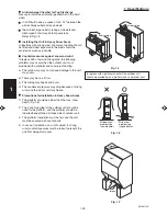
Anchor bolts
(4 pieces)
Fig. 1-1
Out-
door
unit
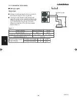
Heat source
Hot air
Exhaust fan
*4
*2
*3
*1
More than 25/64"
More than
3.3 ft.
More than 25/64"
Inlet side C
Outlet side
Fig. 1-2
Fig. 1-3
*1
Inlet side
More than 8"
(field supply)
A
B
(Ground)
Air direction chamber
(Obstruction above unit)
(Obstruction on
inlet side)
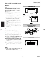
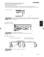
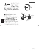
CAUTION
Concerning inlet-side distance “C” (Fig. 1-2)
The minimum for distance “C” is 6" if there are no obstructions on the outlet side
(wall *1 side) and *2 or *4 is not present. In all other cases, the minimum for distance
“C” is 8".
If the unit is installed with the outlet side facing wall *1, then there must be no obstruc-
tions on 2 of the remaining 3 sides: *2, *3, *4.
If wall *1 is on the outlet side (Fig. 1-2), or if obstructions are present on all 3 sides *2,
*3, and *4 (Fig. 1-2), then the minimum distance for “A” and “B” is 80" (Fig. 1-3). Even if
there is no wall on the outlet side, a minimum of 3.3 ft. is required.
Installation requirements
provide a solid base (concrete block, 4" × 16"
beams or equal), a minimum of 6" above ground
level to reduce humidity and protect the unit gainst
possible water damage and decreased service life.
(Fig. 1-4)
use lug bolts or equal to bolt down unit, reducing
vibration and noise.
Outdoor Unit
AVOID:
heat sources, exhaust fans, etc. (Fig. 1-1)
damp, humid or uneven locations
DO:
choose a place as cool as possible.
choose a place that is well ventilated and outside air
temperature does not exceed maximum 115°F
constantly.
allow enough room around the unit for air intake/
exhaust and possible maintenance. (Fig. 1-2)
use lug bolts or equal to bolt down unit, reducing
vibration and noise.
if cooling operation is to be used when the outdoor
air temperature is 23°F or below, install a duct on the
outdoor unit.
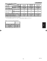
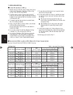
Installation space
Distance between obstructions and the unit air inlet and
outlet must be as shown below.
Содержание 000 BTU Ductless Single Zone Mini-Split Wall-Mounted Heat Pump
Страница 2: ......
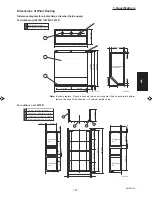
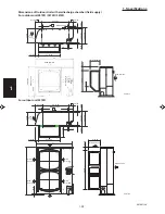
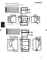
Страница 77: ...1 2 3 4 5 6 I 73 SM831148 1 Specifications 1 4 Dimensional Data B Outdoor Unit CH4272R C4272R ...
Страница 118: ......
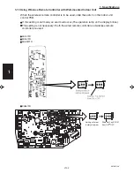
Страница 119: ...III 1 SM831148 3 Electrical data 1 2 3 4 5 6 3 ELECTRICAL DATA 3 1 Indoor Units III 2 3 2 Outdoor Units III 16 ...
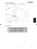
Страница 122: ...1 2 3 4 5 6 III 4 SM831148 3 Electrical data Ceiling Mounted Type TH2672R TH3672R TH4272R Electric Wiring Diagram ...
Страница 123: ...III 5 SM831148 3 Electrical data 1 2 3 4 5 6 Ceiling Mounted Type TH2672R TH3672R TH4272R Schematic Diagram ...
Страница 124: ...1 2 3 4 5 6 III 6 SM831148 3 Electrical data Ceiling Mounted Type THH2672R THH3672R Electric Wiring Diagram ...
Страница 125: ...III 7 SM831148 3 Electrical data 1 2 3 4 5 6 Ceiling Mounted Type THH2672R THH3672R Schematic Diagram ...
Страница 126: ...1 2 3 4 5 6 III 8 SM831148 3 Electrical data Concealed Duct Type UH2672R UH3672R Electric Wiring Diagram ...
Страница 127: ...III 9 SM831148 3 Electrical data 1 2 3 4 5 6 Concealed Duct Type UH2672R UH3672R Schematic Diagram ...
Страница 128: ...1 2 3 4 5 6 III 10 SM831148 3 Electrical data Wall Mounted Type KH2672R ...
Страница 129: ...III 11 SM831148 3 Electrical data 1 2 3 4 5 6 Wall Mounted Type KH2672R Schematic Diagram ...
Страница 130: ...1 2 3 4 5 6 III 12 SM831148 3 Electrical data Wall Mounted Type KH3072R KH3672R Electric Wiring Diagram ...
Страница 131: ...III 13 SM831148 3 Electrical data 1 2 3 4 5 6 Wall Mounted Type KH3072R KH3672R Schematic Diagram ...
Страница 132: ...1 2 3 4 5 6 III 14 SM831148 3 Electrical data Wall Mounted Type KHH2672R Electric Wiring Diagram ...
Страница 133: ...III 15 SM831148 3 Electrical data 1 2 3 4 5 6 Wall Mounted Type KHH2672R Schematic Diagram ...
Страница 134: ...1 2 3 4 5 6 III 16 SM831148 3 Electrical data 3 2 Outdoor Units CH2672R Electric Wiring Diagram ...
Страница 135: ...III 17 SM831148 3 Electrical data 1 2 3 4 5 6 3 2 Outdoor Units CH2672R Schematic Diagram ...
Страница 136: ...1 2 3 4 5 6 III 18 SM831148 3 Electrical data 3 2 Outdoor Units C2672R Electric Wiring Diagram ...
Страница 137: ...III 19 SM831148 3 Electrical data 1 2 3 4 5 6 3 2 Outdoor Units C2672R Schematic Diagram ...
Страница 138: ...1 2 3 4 5 6 III 20 SM831148 3 Electrical data 3 2 Outdoor Units CH3072R CH3672R Electric Wiring Diagram ...
Страница 139: ...III 21 SM831148 3 Electrical data 1 2 3 4 5 6 3 2 Outdoor Units CH3072R CH3672R Schematic Diagram ...
Страница 140: ...1 2 3 4 5 6 III 22 SM831148 3 Electrical data 3 2 Outdoor Units C3072R C3672R Electric Wiring Diagram ...
Страница 141: ...III 23 SM831148 3 Electrical data 1 2 3 4 5 6 3 2 Outdoor Units C3072R C3672R Schematic Diagram ...
Страница 142: ...1 2 3 4 5 6 III 24 SM831148 3 Electrical data 3 2 Outdoor Units CH4272R Electric Wiring Diagram ...
Страница 143: ...III 25 SM831148 3 Electrical data 1 2 3 4 5 6 3 2 Outdoor Units CH4272R Schematic Diagram ...
Страница 144: ...1 2 3 4 5 6 III 26 SM831148 3 Electrical data 3 2 Outdoor Units C4272R Electric Wiring Diagram ...
Страница 145: ...III 27 SM831148 3 Electrical data 1 2 3 4 5 6 3 2 Outdoor Units C4272R Schematic Diagram ...
Страница 146: ......


