


1
2
3
4
5
6
IV-4
SM831148
4. Service procedures
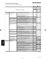
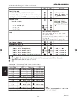
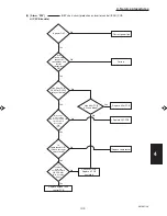
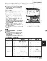
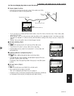
(2) LED Indicator Messages on Outdoor Control PCB
Power ON sequence
1. No communication from indoor units in system
2. Communication received from 1 or more indoor units in system
3. Regular communication OK (Capacity and unit quantity match)
If it is not possible to
advance to 3, repeats 1
→
2.
At 3, changes to normal
control.
P03
Normal operation
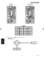
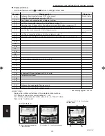
Automatic address setting in progress
Automatic address setting alarm (E15)
Automatic address setting alarm (E20)
Automatic address setting alarm (Other than E15 and E20)
EEPROM error (F31)
Blinking alternately
Blinking simultaneously
Blinking simultaneously
Blinking simultaneously
Alarm
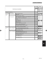
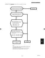
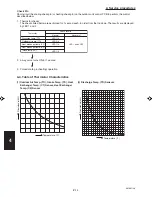
LED 1 blinks M times, then LED 2 blinks N times.
The cycle then repeats.
M = 2: P alarm
6: L alarm
N = Alarm No.
* Refer to
“
1. Examples of alarm display
”
below.
3: H alarm 4: E alarm 5: F alarm
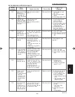
Alternate blinking during alarms
Insufficient gas indicator
Refrigerant recovery mode
Automatic address setting
Displayed during automatic
address setting 1 and initial
communication. After these are
completed, alarm F31 is displayed.
Pre-trip (P20)
Pre-trip (insufficient gas)
Pre-trip (other)
(0.25/0.75)
(0.75/0.25)
(0.25/0.75)
(0.75/0.25)
(0.25/0.75)
(0.75/0.25)
ON
:
:
:
LED 1
LED 2
Remarks
OFF
Blinking (0.25/0.75)
indicates that the lamp illuminates for 0.25 seconds, and then is OFF for 0.75 seconds.
Unless otherwise indicated, the blinking is (0.5/0.5).
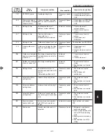
Note:
This table shows example alarms. Other alarms
may also be displayed.
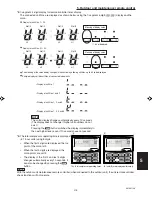
P03
P04
P05
P31
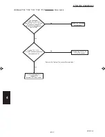
H01
•
E04
•
F07
•
L13
•
( Blinks 2 times )
(
"
)
(
"
)
(
"
)
(Blinks 3 times)
•
(Blinks 4 times)
•
(Blinks 5 times)
•
(Blinks 6 times)
•
(Blinks 3 times)
(Blinks 4 times)
(Blinks 5 times)
(Blinks 31 times)
(Blinks 1 times)
(Blinks 4 times)
(Blinks 7 times)
(Blinks 13 times)
Alarm / Display
LED 1
Alternately
→
→
LED 2
(3) Examples of alarm display (other than E15, E16, and E20)
Содержание 000 BTU Ductless Single Zone Mini-Split Wall-Mounted Heat Pump
Страница 2: ......
Страница 77: ...1 2 3 4 5 6 I 73 SM831148 1 Specifications 1 4 Dimensional Data B Outdoor Unit CH4272R C4272R ...
Страница 118: ......
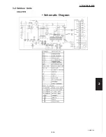
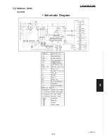
Страница 119: ...III 1 SM831148 3 Electrical data 1 2 3 4 5 6 3 ELECTRICAL DATA 3 1 Indoor Units III 2 3 2 Outdoor Units III 16 ...
Страница 122: ...1 2 3 4 5 6 III 4 SM831148 3 Electrical data Ceiling Mounted Type TH2672R TH3672R TH4272R Electric Wiring Diagram ...
Страница 123: ...III 5 SM831148 3 Electrical data 1 2 3 4 5 6 Ceiling Mounted Type TH2672R TH3672R TH4272R Schematic Diagram ...
Страница 124: ...1 2 3 4 5 6 III 6 SM831148 3 Electrical data Ceiling Mounted Type THH2672R THH3672R Electric Wiring Diagram ...
Страница 125: ...III 7 SM831148 3 Electrical data 1 2 3 4 5 6 Ceiling Mounted Type THH2672R THH3672R Schematic Diagram ...
Страница 126: ...1 2 3 4 5 6 III 8 SM831148 3 Electrical data Concealed Duct Type UH2672R UH3672R Electric Wiring Diagram ...
Страница 127: ...III 9 SM831148 3 Electrical data 1 2 3 4 5 6 Concealed Duct Type UH2672R UH3672R Schematic Diagram ...
Страница 128: ...1 2 3 4 5 6 III 10 SM831148 3 Electrical data Wall Mounted Type KH2672R ...
Страница 129: ...III 11 SM831148 3 Electrical data 1 2 3 4 5 6 Wall Mounted Type KH2672R Schematic Diagram ...
Страница 130: ...1 2 3 4 5 6 III 12 SM831148 3 Electrical data Wall Mounted Type KH3072R KH3672R Electric Wiring Diagram ...
Страница 131: ...III 13 SM831148 3 Electrical data 1 2 3 4 5 6 Wall Mounted Type KH3072R KH3672R Schematic Diagram ...
Страница 132: ...1 2 3 4 5 6 III 14 SM831148 3 Electrical data Wall Mounted Type KHH2672R Electric Wiring Diagram ...
Страница 133: ...III 15 SM831148 3 Electrical data 1 2 3 4 5 6 Wall Mounted Type KHH2672R Schematic Diagram ...
Страница 134: ...1 2 3 4 5 6 III 16 SM831148 3 Electrical data 3 2 Outdoor Units CH2672R Electric Wiring Diagram ...
Страница 135: ...III 17 SM831148 3 Electrical data 1 2 3 4 5 6 3 2 Outdoor Units CH2672R Schematic Diagram ...
Страница 136: ...1 2 3 4 5 6 III 18 SM831148 3 Electrical data 3 2 Outdoor Units C2672R Electric Wiring Diagram ...
Страница 137: ...III 19 SM831148 3 Electrical data 1 2 3 4 5 6 3 2 Outdoor Units C2672R Schematic Diagram ...
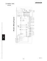
Страница 138: ...1 2 3 4 5 6 III 20 SM831148 3 Electrical data 3 2 Outdoor Units CH3072R CH3672R Electric Wiring Diagram ...
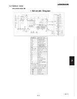
Страница 139: ...III 21 SM831148 3 Electrical data 1 2 3 4 5 6 3 2 Outdoor Units CH3072R CH3672R Schematic Diagram ...
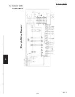
Страница 140: ...1 2 3 4 5 6 III 22 SM831148 3 Electrical data 3 2 Outdoor Units C3072R C3672R Electric Wiring Diagram ...
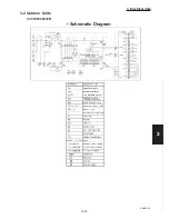
Страница 141: ...III 23 SM831148 3 Electrical data 1 2 3 4 5 6 3 2 Outdoor Units C3072R C3672R Schematic Diagram ...
Страница 142: ...1 2 3 4 5 6 III 24 SM831148 3 Electrical data 3 2 Outdoor Units CH4272R Electric Wiring Diagram ...
Страница 143: ...III 25 SM831148 3 Electrical data 1 2 3 4 5 6 3 2 Outdoor Units CH4272R Schematic Diagram ...
Страница 144: ...1 2 3 4 5 6 III 26 SM831148 3 Electrical data 3 2 Outdoor Units C4272R Electric Wiring Diagram ...
Страница 145: ...III 27 SM831148 3 Electrical data 1 2 3 4 5 6 3 2 Outdoor Units C4272R Schematic Diagram ...
Страница 146: ......