


II-11
SM831148
1
2
3
4
5
6
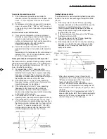
2. Processes and functions
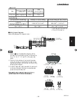
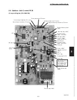
3P plug (black): Terminal plug for the communications line
• At the time of shipment from the factory, the short-circuiting socket (2P, black) is
installed between pins 1 and 2 on the terminal plug (terminal = yes).
• When central control is used for multiple systems, leave the short-circuiting socket in
place only on the outdoor unit with a system address of 1. At all other outdoor units
(other than unit No. 1), move the short-circuiting socket to between 2 and 3 (terminal =
no). If multiple short-circuiting sockets remain in place during central control, a com-
munications failure will occur.
• In the case of a single system only (system address = 0), do not remove the short-
circuiting socket. (Alarm "E04" will occur.)
2P plug (white): Enables operation in quiet mode.
• The outdoor unit fan and compressor frequencies are subject to limits during operation.
• Low-noise operation is enabled when the relay is turned ON.
Outdoor unit control PCB
Note 1:
The maximum length of the wiring between the outdoor unit PCB and the relay is
2 m.
• Lead wire with 2P plug (special-order part: WIRE K/ 623-161-2098)
• Relay, field supply, contact input specifications: DC 5 V, 0.5 mA (Recommended relay:
Fuji Electric HH62SW, compatible with micro contacts)
• Use a commercially available timer (such as the Omron H5 daily time switch).
Terminal plug
(CN015)
Quiet mode
(CN028)
Example of wiring
1
2
CN028
1
2
Quiet mode
Relay (field supply)
Power
External contact
(timer input, etc.: field supply)
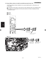
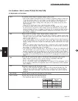
Table 1. Method of System Address Setting
[S002 (rotary, black), S003 (2P DIP switch, green or blue)]
1
1
2
3
4
5
6
7
8
9
10
11
12
13
14
15
16
17
18
19
20
21
22
23
24
25
26
27
28
29
30
0
1
2
3
4
5
6
7
8
9
0
1
2
3
4
5
6
7
8
9
0
1
2
3
4
5
6
7
8
9
0
OFF
OFF
OFF
OFF
OFF
OFF
OFF
OFF
OFF
OFF
ON
ON
ON
ON
ON
ON
ON
ON
ON
ON
OFF
OFF
OFF
OFF
OFF
OFF
OFF
OFF
OFF
OFF
ON
OFF
OFF
OFF
OFF
OFF
OFF
OFF
OFF
OFF
OFF
OFF
OFF
OFF
OFF
OFF
OFF
OFF
OFF
OFF
OFF
ON
ON
ON
ON
ON
ON
ON
ON
ON
ON
ON
2P (20s-digit place)
Outdoor system
address No.
1 system only
Central
control
S002 setting
(system address switch)
S003 setting
1P (10s-digit place)
System
controller
Out-
door
Out-
door
Out-
door
Out-
door
In-
door
In-
door
In-
door
In-
door
Fig. 6
Содержание 000 BTU Ductless Single Zone Mini-Split Wall-Mounted Heat Pump
Страница 2: ......
Страница 77: ...1 2 3 4 5 6 I 73 SM831148 1 Specifications 1 4 Dimensional Data B Outdoor Unit CH4272R C4272R ...
Страница 118: ......
Страница 119: ...III 1 SM831148 3 Electrical data 1 2 3 4 5 6 3 ELECTRICAL DATA 3 1 Indoor Units III 2 3 2 Outdoor Units III 16 ...
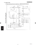
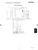
Страница 122: ...1 2 3 4 5 6 III 4 SM831148 3 Electrical data Ceiling Mounted Type TH2672R TH3672R TH4272R Electric Wiring Diagram ...
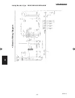
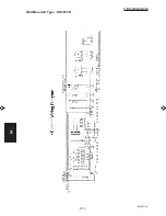
Страница 123: ...III 5 SM831148 3 Electrical data 1 2 3 4 5 6 Ceiling Mounted Type TH2672R TH3672R TH4272R Schematic Diagram ...
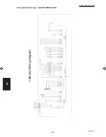
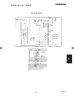
Страница 124: ...1 2 3 4 5 6 III 6 SM831148 3 Electrical data Ceiling Mounted Type THH2672R THH3672R Electric Wiring Diagram ...
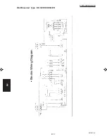
Страница 125: ...III 7 SM831148 3 Electrical data 1 2 3 4 5 6 Ceiling Mounted Type THH2672R THH3672R Schematic Diagram ...
Страница 126: ...1 2 3 4 5 6 III 8 SM831148 3 Electrical data Concealed Duct Type UH2672R UH3672R Electric Wiring Diagram ...
Страница 127: ...III 9 SM831148 3 Electrical data 1 2 3 4 5 6 Concealed Duct Type UH2672R UH3672R Schematic Diagram ...
Страница 128: ...1 2 3 4 5 6 III 10 SM831148 3 Electrical data Wall Mounted Type KH2672R ...
Страница 129: ...III 11 SM831148 3 Electrical data 1 2 3 4 5 6 Wall Mounted Type KH2672R Schematic Diagram ...
Страница 130: ...1 2 3 4 5 6 III 12 SM831148 3 Electrical data Wall Mounted Type KH3072R KH3672R Electric Wiring Diagram ...
Страница 131: ...III 13 SM831148 3 Electrical data 1 2 3 4 5 6 Wall Mounted Type KH3072R KH3672R Schematic Diagram ...
Страница 132: ...1 2 3 4 5 6 III 14 SM831148 3 Electrical data Wall Mounted Type KHH2672R Electric Wiring Diagram ...
Страница 133: ...III 15 SM831148 3 Electrical data 1 2 3 4 5 6 Wall Mounted Type KHH2672R Schematic Diagram ...
Страница 134: ...1 2 3 4 5 6 III 16 SM831148 3 Electrical data 3 2 Outdoor Units CH2672R Electric Wiring Diagram ...
Страница 135: ...III 17 SM831148 3 Electrical data 1 2 3 4 5 6 3 2 Outdoor Units CH2672R Schematic Diagram ...
Страница 136: ...1 2 3 4 5 6 III 18 SM831148 3 Electrical data 3 2 Outdoor Units C2672R Electric Wiring Diagram ...
Страница 137: ...III 19 SM831148 3 Electrical data 1 2 3 4 5 6 3 2 Outdoor Units C2672R Schematic Diagram ...
Страница 138: ...1 2 3 4 5 6 III 20 SM831148 3 Electrical data 3 2 Outdoor Units CH3072R CH3672R Electric Wiring Diagram ...
Страница 139: ...III 21 SM831148 3 Electrical data 1 2 3 4 5 6 3 2 Outdoor Units CH3072R CH3672R Schematic Diagram ...
Страница 140: ...1 2 3 4 5 6 III 22 SM831148 3 Electrical data 3 2 Outdoor Units C3072R C3672R Electric Wiring Diagram ...
Страница 141: ...III 23 SM831148 3 Electrical data 1 2 3 4 5 6 3 2 Outdoor Units C3072R C3672R Schematic Diagram ...
Страница 142: ...1 2 3 4 5 6 III 24 SM831148 3 Electrical data 3 2 Outdoor Units CH4272R Electric Wiring Diagram ...
Страница 143: ...III 25 SM831148 3 Electrical data 1 2 3 4 5 6 3 2 Outdoor Units CH4272R Schematic Diagram ...
Страница 144: ...1 2 3 4 5 6 III 26 SM831148 3 Electrical data 3 2 Outdoor Units C4272R Electric Wiring Diagram ...
Страница 145: ...III 27 SM831148 3 Electrical data 1 2 3 4 5 6 3 2 Outdoor Units C4272R Schematic Diagram ...
Страница 146: ......