7
Instruction Manual for BIO-WALL™
1-888-726-8869
www.sanuvox.com
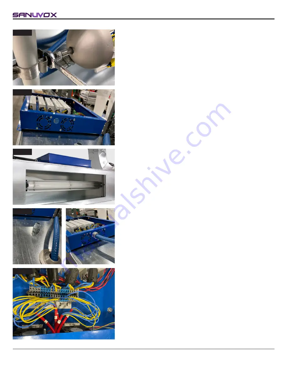
STEP 12
STEP 13
STEP 14
STEP 15
12. Slip the end of the cable through the hole and gently pull the cable out
of the conduit.
NOTE:
At some point, you will be in a position to lift the extrusion and
gently slide it into the mounting clips. Be sure to leave some slack in the
cable inside the conduit.
You can now tighten the nuts that hold the extrusion into the clamps.
Install Ballast Box on Slected Surface
13. Remove the case cover by turning the 4 screws to the left. Lay it aside.
14. Fix the box to the surface using the 6 self-tapping screws provided. The
box can be installed vertically or horizontally. Make sure the box is within
reach of the wire for the connection.
Connect Cable to Ballast Box
15. Remove the ring from the connector and pass the end of the cable
through the opening provided in the box, between the two fans. Secure it
in place by putting the ring back in place. The rest of the cable should be
secured in place with clamps (not supplied).
STEP 16
16. The section of the cable in the box is made up of 20 wires, ie 5 wires of
4 strands – 2 red and 2 blue. Just nearby is a terminal block to which the
5 ballasts are connected, the first being at the very bottom.
Select the wire identified #1, separate the red and blue strands and plug
them separately into the section of the terminal block relating to ballast
#1. Be sure to plug the red wires into the sections adjoining the red wires
and the blue ones the same, adjoining the blue wires.
NOTE:
To simplify your task, you can use a mini flat-blade screwdriver: if
you push it into the square opening at the side of the wire, the insertion
or removal of the wire will be easier. If you remove the blade, the wire will
get stuck.
Содержание Bio-Wall MAX
Страница 9: ...ELECTRICAL DIAGRAM ...
Страница 10: ......


