


57
REV:4
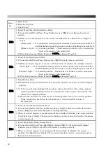
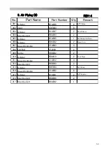
No.
Part Name
Part Number
Q'ty
Remark
201 Cylinder
B0K016
1
Front Press Slide
202
Cylinder Sensor
B5A003
4
203 Joint
C0C054
2
204 Floating Joint
E5L001
1
Cylinder
B1H001
1
Front Press
206 Cylinder Sensor
B5A004
2
207 Speed Controller
C1A024
3
208 Speed Controller
C1A026
1
Cylinder
B2C008
1
Rear Press
210 Cylinder
B0U009
1
Shoulder Press
211 Cylinder Sensor
B5A003
2
212 Speed Controller
C1A012
2
213 Knuckle Joint
B6A004
1
Cylinder
B1A007
1
Neck
215 Joint
C0C161
6
216 Cylinder
B1L003
2
217 Knuckle Joint
B6B007
2
218 Air Combination
D0F008
1
219 Air Gauge
D1C001
1
220 Joint
C0C012
1
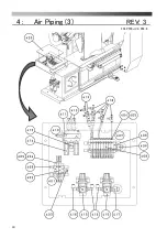
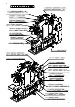
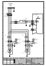
2. Air Piping (1)
205
209
214
Содержание LP-570E-V2
Страница 54: ...54 Motor Operation Diagram 1 Motor Operation Diagram REV 4...
Страница 56: ...56 Air Piping 1 2 Air Piping 1 REV 3 3DLP570E V2 052 2...
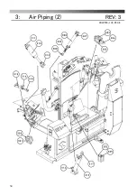
Страница 58: ...58 Air Piping 2 3 Air Piping 2 REV 3 3DLP550J V2 053 6...
Страница 60: ...60 Air Piping 3 4 Air Piping 3 REV 3 3DLP550J V2 054 6...
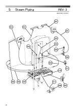
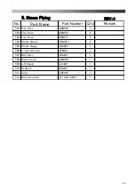
Страница 62: ...62 Steam Piping 5 Steam Piping REV 3 3DLP570E V2 055 1...
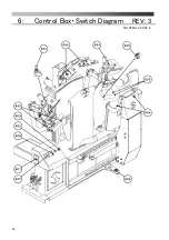
Страница 64: ...64 Control Box Switch Diagram 6 Control Box Switch Diagram REV 3 3DLP550J V2 056 6...
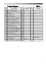
Страница 66: ...66 Cover Diagram 7 Cover Diagram REV 3 3DLP570E V2 057 3...
Страница 69: ......
Страница 70: ......
Страница 71: ......
Страница 72: ......
Страница 73: ......
Страница 74: ......
Страница 75: ......
Страница 76: ...LP 570E V2X Rev 6 2019 6 1 2 B...


