


CP3005 – User Guide Rev. 1.8
// 90
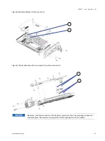
Figure 35: CP3005 with Front Panel, MMEXT-XMC02 Extension Module and XMC Module
1.
Ensure that no power is applied to the CP3005 and disconnect any interfacing cables that may be connected
to the board before proceeding.
Even though power may be removed from the system, the CP3005 front panel cables and,
when installed, the RIO transition module front panel cables may have power applied which
comes from an external source. In addition, these cables may be connected to devices that
can be damaged by electrostatic discharging or short-circuiting of pins. It is the
responsibility of the system designer or integrator to ensure that appropriate measures are
taken to preclude damage to the system or injury to personnel which may arise from the
handling of these cables (connecting or disconnecting). Kontron disclaims all liability for
damages or injuries resulting from failure to comply with the above.
Remove the front panel by unscrewing the following screws that are retaining the front panel to the CP3005 board.
2.
Search for the location of the above-mentioned screws.
(a) and (b) near the VGA connector on the front panel
(c) and (d) near the XMC slot on the front panel
(e) and (f) on the board’s solder side near the front panel
Remove the MMEXT-XMC02 from the CP3005 by unscrewing the (g), (h), (i) and (j) screws.
Turn the XMC module component-side down, align its XMC connector with the MMEXT05’s XMC connector, J1, and
gently press down. Secure the XMC module to the MMEXT-XMC02 by inserting the four screws (k), (l), (m), and (n)
supplied with the XMC module through the MMEXT05-XMC02’s mounting holes into the XMC module’s standoffs and
tightening them. Search for the location of the above-mentioned mounting holes.