


CP3005 – User Guide Rev. 1.8
// 39
3.9.3.2.
General Purpose LEDs
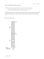
The General Purpose LEDs (LED3..0) are designed to indicate the boot-up POST code after which they are available to
the application. If the LED3..0 are lit red during boot-up, a failure is indicated. In this event, please contact Kontron for
further assistance.
Table 14: General Purpose LEDs Function
LED
Color
Function During
Boot-Up
Function During Uefi
Bios Post (If Post Code
Config. Is Enabled)
Function After Boot-Up
LED3
red
Power failure
--
General Purpose or Port
80 Default: General
Purpose
green
--
uEFI BIOS POST bit 3 and
bit 7
red+green
--
--
LED2
red
CPU catastrophic
error
CPU catastrophic error
General Purpose or Port
80
Default: General Purpose
green
--
uEFI BIOS POST bit 2 and
bit 6
red+green
--
--
LED1
red
Hardware reset
--
General Purpose or Port
80
Default: General Purpose
green
--
uEFI BIOS POST bit 1 and
bit 5
red+green
--
--
LED0
red
uEFI BIOS boot
failure
--
General Purpose or Port
80
Default: General Purpose
green
--
uEFI BIOS POST bit 0 and
bit 4
red+green
--
--
The bit allocation for Port 80 is the same as for the POST code.
How to read the 8-Bit POST Code
Due to the fact that only 4 LEDs are available and 8 bits must be displayed, the POST code output is multiplexed on
the General Purpose LEDs.
Table 15: POST Code Sequence
State
General Purpose Leds
0
All LEDs are OFF; start of POST sequence
1
High nibble
2
Low nibble; state 2 is followed by state 0
The following is an example of the General Purpose LEDs’ operation if the POST configuration is enabled.
Table 16: POST Code Example
LED3
LED2
LED1
LED0
Result
High Nibble
off (0)
on (1)
off (0)
off (0)
0x4