CP3005 – User Guide Rev. 1.8
// 44
Bitfield
Description
2
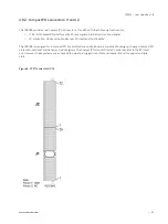
DIP3
DIP switch SW1, switch 3 (reset configuration):
0 = Switch on (reset does a power cycle)
1 = Switch off (standard reset configuration)
1
DIP2
DIP switch SW1, switch 2 (select SPI flash):
0 = Switch on (boot from recovery SPI boot flash)
1 = Switch off (boot from standard SPI boot flash)
0
DIP1
DIP switch SW1, switch 1 (POST code indication on LED0..3):
0 = Switch on (boot-up without POST code indication on LED0..3)
1 = Switch off (boot-up with POST code indication on LED0..3)
4.3.2.
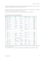
Status Register 1 (STAT1)
The Status Register 1 holds board-specific status information.
Table 20: Status Register 1 (STAT1)
Address
0x281
Bit
7
6
5
4
3
2
1
0
Name
C66EN
Reserved
R
000
CSYS
CENUM
CFAL
CDEG
Access
R
R
R
R
R
Reset
N/A
N/A
N/A
N/A
N/A
Bitfield
Description
7
C66EN
CPCI PCI speed (M66EN signal):
0 = 33 MHz
1 = 66 MHz
3
CSYS
CPCI system slot identification (SYSEN signal):
0 = Installed in a system slot
1 = Installed in a peripheral slot
2
CENUM
CPCI system enumeration (ENUM signal):
0 = Indicates the insertion or removal of a hot swap peripheral board
when the CP3005 operates as the system controller board
1 = No hot swap event
1
CFAL
CPCI power supply status (FAL signal):
0 = Power supply failure
1 = Power in normal state
0
CDEG
CPCI power supply status (DEG signal):
0 = Power derating
1 = Power in normal state


