S&C Scada-Mate SD Скачать руководство пользователя страница 19

S&C Instruction Sheet 775-510   

19

STEP  25.  

Close the disconnect by pushing the operating  

ring into the contact. See Figure 19. When the 
blade contact latch is completely closed, the 
operating ring will tilt backward into the blade 
contact. Disengage the hookstick from the 
operating ring. Repeat with the remaining two 
disconnects. The switch can now be closed.

The disconnects are mechanically blocked  

in the 

Closed

 position while the switch is in the 

Closed

 state.

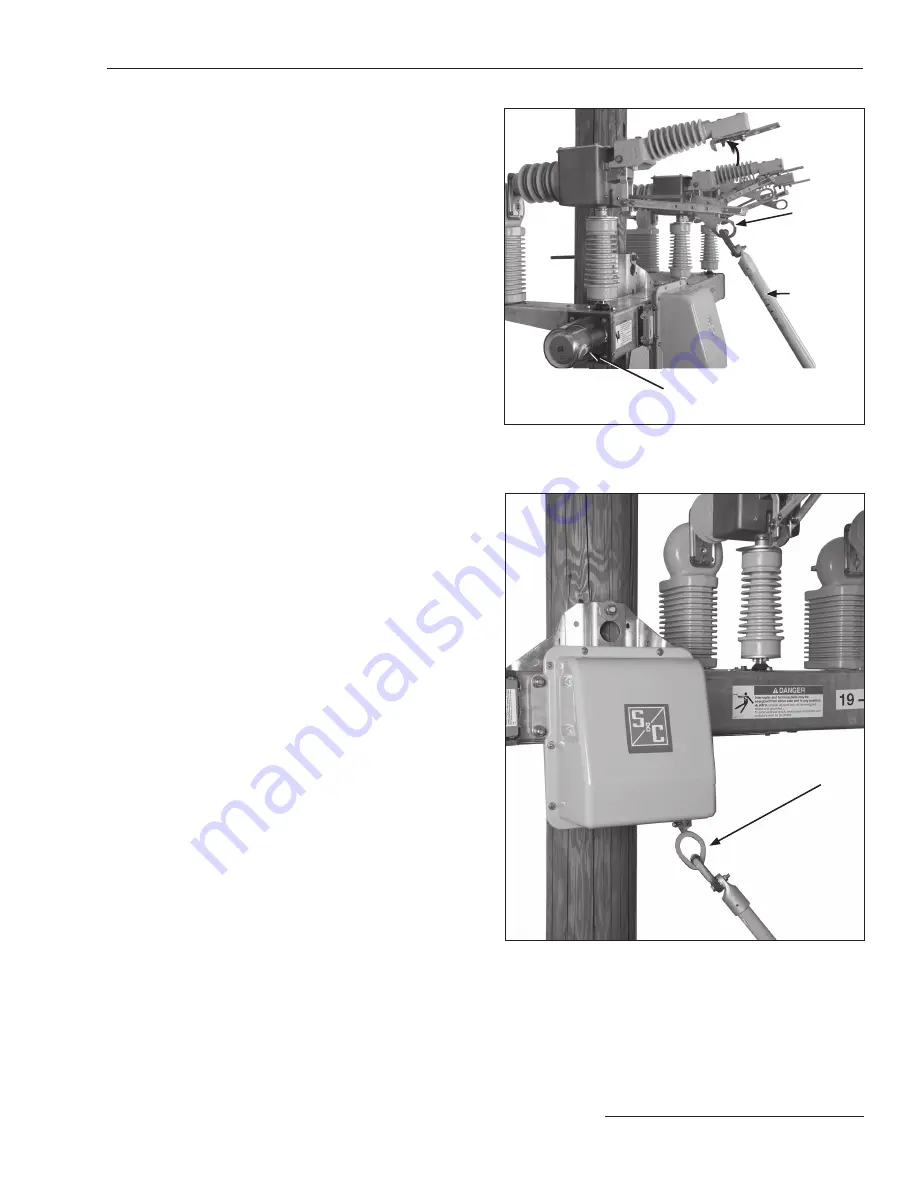
Emergency Manual Operation

STEP  26.  

Scada-Mate SD Switches are capable of manual 

interrupter operation. In the event of electrical 
power loss, a standard or extendible hookstick is 
used to open and close the interrupters. If the 
spring is fully discharged, pull on the operating 
mechanism pull-ring with the hookstick seven to 
nine times to effect a change of state. If the spring 
is partially charged, a single pull will change the 
interrupter position. See Figure 20. 

Figure 19. Push the blade into contact.

Figure 20. Manual operation with a hookstick.

Operation—For Switches with Power Operator

Pull ring downward

Hookstick

Operating 

ring

Push ring upward

Indicator in 

Open position

Содержание Scada-Mate SD

Страница 1: ...eplacement Instructions and Labels 3 Location of Safety Labels and Tags 4 Safety Precautions 5 Shipping and Handling Packing 6 Inspection 6 Handling 7 Installation Inserting Pole Mounting Hardware 8 S...

Страница 2: ...retrieve and refer to this publication Proper Application WARNING The equipment in this publication is only intended for a specific application The application must be within the ratings furnished for...

Страница 3: ...cautions are not followed NOTICE NOTICE identifies important procedures or requirements that can result in product or property damage if instructions are not followed Following Safety Instructions If...

Страница 4: ...ads may be energized from either side and in any position G 6812 D WARNING Electrocution Hazard Switch and control unit enclosure must be installed and grounded ONLY by qualified personnel G 6815 E WA...

Страница 5: ...Switching Systems contain fast moving parts that can severely injure fingers Do not remove or disassemble operating mechanisms or remove access panels on the Scada Mate SD switch base unless directed...

Страница 6: ...ese values must be programmed into the remote terminal unit RTU installed with the switch if applicable to apply correction for the unit to unit variations in the sensors The S C Sensor information is...

Страница 7: ...EP 2 Secure the lifting slings to the switch before unbolting the switch from the crate Remove all packing materials before lifting the switch Shipping and Handling Lifting bracket extended NOTICE Do...

Страница 8: ...erline distance of the holes must be 14 inches 356 mm STEP 4 Insert two inch diameter through bolts not furnished in the holes drilled in Step 3 Secure these bolts loosely with necessary washers and n...

Страница 9: ...to uncrate the switch before lifting may cause damage to the switch or personal injury Installing the Optional Pole Band and J Bolts Conduct the following steps to install the optional pole band and...

Страница 10: ...ting the end of a number 2 AWG wire or two number 6 AWG wires or wires having an equivalent cross sectional area to the grounding lug on the pole saddle See Figure 6 Insert the ground wire into the gr...

Страница 11: ...ors on the terminal pads use the following procedure to prepare their surfaces STEP 10 Do not wire brush Scada Mate SD switch terminal pads They are plated and wire brushing will scratch the protectiv...

Страница 12: ...to the terminal pads For installation instructions refer to S C Drawing RD 6794 STEP 13 To install the optional wildlife protection components first prepare the surfaces of the terminal pads and conn...

Страница 13: ...Mate SD switches STEP 15 Ground the enclosure by solidly connecting one number 6 AWG wire or wires of equivalent cross sectional area to the ground lug on the back of the enclosure Solidly connect th...

Страница 14: ...ol unit Locate the connector receptacle on the front of the switch base and remove the dust cover c Remove the sensor shorting blocks from the receptacle and attach the control cable plug d Secure the...

Страница 15: ...rol cable at the drip loop and at the switch connection b Attach the control cable along the length of the utility pole and secure the control cable to the utility pole using suitable guards or clamps...

Страница 16: ...Electric Company Use the following procedure to energize the power operated switch STEP 20 After making all user connections to the control unit if applicable in accordance with the S C instruction sh...

Страница 17: ...remote operation STEP 22 Place the LOCAL REMOTE switch inside the control unit in the Remote position Refer to the instructionsheetfurnishedwiththecontrolunit The Scada Mate SD switch can now only be...

Страница 18: ...ow the procedure below using a conventional insulated hookstick or S C Universal Pole and Pole Extension if required fit ted with a heavy duty hook tool such as the S C Substation Prong or equivalent...

Страница 19: ...gency Manual Operation STEP 26 Scada Mate SD Switches are capable of manual interrupter operation In the event of electrical power loss a standard or extendible hookstick is used to open and close the...

Страница 20: ...uffix W slide the tap cover backfarenoughtogainaccesstotheterminalpads Then remove the upper and lower terminal pad covers to permit the removal of the phase conductors Retain the covers for reinstall...

Отзывы: