S&C Instruction Sheet 766-510
9
Inspection and Handling
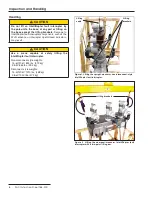
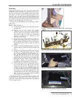
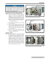
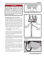
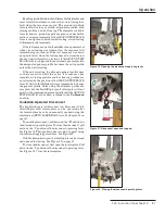
Figure 3. Unbolting a fault interrupter from the shipping
supports.
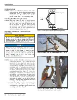
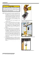
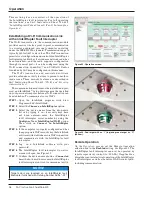
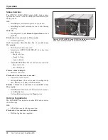
Figure 4. Removing plastic covers from module bays in base.
Plastic
covers
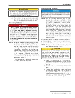
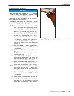
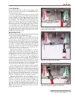
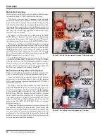
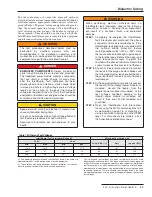
Figure 5. Placing the dust cover in the module bay.
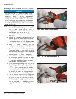
Figure 6. Set the dust cover on the shelf in the bay.
Uncrating
Before uncrating the unit, note that either side of the
IntelliRupter fault interrupter can be the source side or
the load side. However, when supplied with a three-phase
disconnect, the disconnect is typically placed on the
load side. Also consider whether the IntelliRupter fault
Interrupter has one or two integral power modules. If only
one module is present, make certain the lead from the
module to the bushing faces the source-side.
To uncrate the IntelliRupter fault interrupter, follow
these steps:
STEP 1.
Remove the crate.
(a) Cut the plastic cable ties securing the top of the
shipping crate.
(b) Remove the top, and remove the cartons
containing the protection and control module
and the communication module. Set these aside,
and remove and set aside the waterproof
envelope containing the installation and
operating instructions.
(c) Swing up the two lifting brackets as shown in
Figure 1 and in Figure 2 on page 8—Figure 1 for
the standard IntelliRupter fault interrupter
models and Figure 2 for the compact-crossarm
models.
(d) Attach a suitable sling through the holes in the
lifting brackets. Lift the unit until the sling is just
taut.
(e) Unbolt the fault interrupter base from its skid.
See Figure 3. The 4x4 shipping supports can be
left on if the IntelliRupter fault interrupter is to
be set on the ground for any reason. Do not set the
IntelliRupter fault interrupter on soft or muddy
ground because doing so may damage the
indicators located on the bottom of the fault
interrupter. Slowly and carefully hoist the
IntelliRupter fault interrupter out of the crate.
(f) When the unit is a few feet off the ground, remove
the two SD-6183 plastic dust covers from the
module bays in the base. See Figure 4 for the
location. Store the covers inside the module bay
as shown in Figures 5 and 6. If the modules are
not going to be installed immediately after
mounting the switch to the utility pole, leave the
dust covers in place to protect against wildlife
intrusion into the module bays.
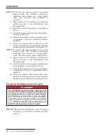
The lifting brackets are permanently attached to the
IntelliRupter fault interrupter base. After installation is
completed, remove the tie wrap and fold down the brackets
to the storage position.
Power
Module

