16
S&C Instruction Sheet 766-510
Installation
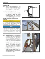
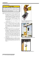
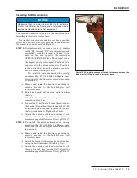
STEP 14.
To install the antenna bracket for catalog
number suffix “-B2” (900-MHz, 9-dBd gain,
directional Yagi antenna) or catalog number
suffix “-B3” (bracket only) mounted in
position 1:
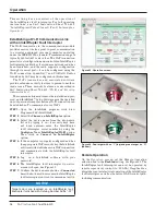
(a) Remove and retain the hardware attaching the
antenna bracket to the IntelliRupter fault
interrupter base.
(b) Rotate the bracket 180 degrees, as viewed from
the top.
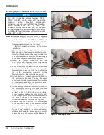
(c) Attach the bracket to the base using the hardware
removed in Step 14 (a).
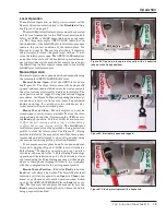
(d) Mount the Yagi antenna or user-supplied antenna,
as applicable, to the mast using the hardware
provided.
(e) Attach the antenna cable, and secure it with
three plastic cable ties (provided) at the locations
marked on page 2 of Reference Drawing RD-6927.
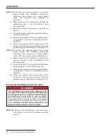
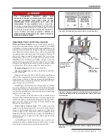
STEP 15.
To install the antenna bracket for catalog
number suffix “-B2” (900-MHz, 9-dBd gain,
directional Yagi antenna) or catalog number
suffix “-B3” (bracket only) mounted in position 2:
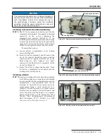
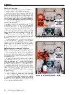
(a) Remove and retain the hardware attaching the
antenna bracket to the IntelliRupter fault
interrupter base.
(b) Attach the bracket to the opposite end of the base
using the hardware removed in Step 15 (a).
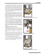
(c) Mount the Yagi antenna or user-supplied antenna,
as applicable, to the mast using the hardware
provided.
(d) Attach the antenna cable, and secure it with
three plastic cable ties (provided) at the locations
marked on page 2 of Reference Drawing RD-6927.
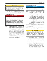
Energizing IntelliRupter Fault Interrupter
DANGER
The IntelliRupter fault interrupter base must be
connected to a suitable earth ground at the base of
the utility pole before energizing the IntelliRupter
fault interrupter, and at all times when energized.
The ground wire(s) must be bonded to the system
neutral, if present, in accordance with this instruction
sheet.
Failure to observe these instructions can
result in serious personal injury or death.
STEP 16.
Energize the IntelliRupter fault interrupter
according to your utility’s standard operating
practice.

