background image


User Guide 


38

3-6-8 

Split  zoom  and  Full  Screen  zoom


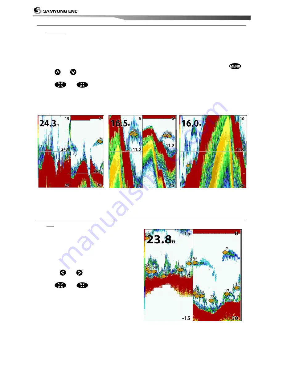
Split zoom   
Split  zoom
  mode  expands  selected  area  of 
the  single  frequency  by  VRM(Variable  Range 
Mark).  The  left  side  displays  zoomed  section 
of  current  sonar  record.  The  VRM  of  right 
side indicates the zoom section area.   
• Press 

  or 

  to change the zoom 

range.   

• Press 


or 


to change the depth 

range.   


Bottom lock 


If Bottom lock is on, the zoom depth (the 
depth of the zoom section) is adjusted 
automatically so that the bottom is always 
displayed in the zoom section. 
• To turn Bottom lock on or off press 


Full Screen zoom   
Full screen zoom
 displays only the zoom 
section of split zoom. 

[Split zoom]                                  [Bottom Lock]                            [Full screen zoom] 


3-6-9 

Split  bottom


Split bottom display provides a normal 
picture on the right half and a selectable 
range over and below the bottom line is 
expanded onto the left half of the screen. 
This mode is useful for detecting bottom 
fishes.   
 
• Use the 


or 

  keys to adjust the 

zoom range. 

• Press 


or 


to change the range   

•  The  VRM  moves  up  and  down  to  calculate 

the bottom depth automatically. 


Содержание Nf100

Страница 1: ...User Guide 1...

Страница 2: ...User Guide 2...

Страница 3: ...lay to UV rays may shorten the life of the liquid crystals used in you plotter This limitation is due to the current technology of the LCD display Avoid overheating which may cause loss of contrast an...

Страница 4: ...User Guide 4...

Страница 5: ...26 3 4 2 Latitude and Longitude 27 3 4 3 Chart scale 27 3 4 4 NAVIONICS Search 27 3 4 5 SAMYUNG Map Search 28 3 4 6 Symbols and information 28 3 4 7 Introduction to navigating 28 3 4 8 Going to a way...

Страница 6: ...5 3 11 Satellites 46 3 11 1 Satellite Information 46 3 12 Tides 47 3 13 AIS 48 3 13 1 Viewing AIS Vessels 48 3 13 2 AIS Windows 48 3 14 DSC 50 3 14 1 Distress 50 3 14 2 Poll 51 3 15 Navtex 52 3 16 Eng...

Страница 7: ...8 Magnetic Variation 58 4 5 Track Log Settings 59 4 5 1 Track 59 4 5 2 Log 59 4 6 Memory Settings 60 4 6 1 Save 60 4 6 2 Load 60 4 6 3 Delete 60 4 6 4 Format 61 4 6 5 Screen Snap Shot 61 4 7 AIS Setti...

Страница 8: ...NECTIONS 66 5 1 OPTIONAL PART 66 5 2 CONNECTION 69 5 3 Power supply DATA cable 69 5 4 Alert equipment 69 5 5 GPS ANTENNA 70 5 5 1 External antenna 70 5 5 2 Internal antenna 70 5 6 NMEA 0183 70 5 7 DAT...

Страница 9: ...satellites providing precise location data with a host of navigation features Some functions require optional units and sensors installed on your boat The chart plotter can be connected to external de...

Страница 10: ...RMC RPM VHW VTG VWT ZDA NMEA 2000 input System date and time PGN126992 Vessel Heading PGN127250 Engine parameters Rapid Update PGN127488 Engine parameters Dynamic PGN127489 Trip parameters Engine PGN...

Страница 11: ...0183 Speed 4800 9600 38400 NMEA 2000 NMEA 0183 Input DBK DBS DBT DPT GGA GLL GNS GGA GSV HDG HDT MDA MTA MTW MWD MWV RMC RPM VHW VTG VWT ZDA NMEA 2000 Input System date and time PGN126992 Vessel Headi...

Страница 12: ...uide ENG N100 QSG 50 200KHZ Transducer B45 X 1 4 Optional Component Model Part Number List GPS Antenna BNC Plug GPS Antenna support GPS Antenna GPS Antenna support SAN 60 20m GPS Antenna cable 20m GPS...

Страница 13: ...g Find the appropriate place to install considering GPS Chart plotter s weight and user convenience Mounting the display unit 1 Hold the display unit and place the screw between the display and the kn...

Страница 14: ...large the chart Display Set to the display you wish to show Reduce the size of chart Directional key Move cursor from display Can review the record of fish finding from the fish finder display Enter S...

Страница 15: ...t the display Under Sonar when you press it the noise menu pops up The electronic buoy menu appears on the bottom of the screen You may set the track The menu appears on the bottom for you to choose Y...

Страница 16: ...User Guide 16 REM 350...

Страница 17: ...over and press SD card to remove 3 Close the cover Inserting USB 1 Refer to check the terminal carefully and insert the usb Removing USB 1 Hold the USB and pull it out Insert NAVIONICS SD and USB accu...

Страница 18: ...6 Data Bar Data bar displays useful navigational information at the top of the display Displaying Data bar 1 Press and select Data bar 2 Select Data bar Setting the data displayed in the bar 1 Press a...

Страница 19: ...is a compass needle at top right side When the compass is displayed COG is always displayed in data field Also when you are navigating to a point COG and BRG is always displayed in data bar Tip COG T...

Страница 20: ...elect the window you wish to add Changing window size 1 Press and select Split icon on bottom 2 Press or to change the size of the windows Removing the window 1 Press and hold down to select a window...

Страница 21: ...ommonly used windows are called favorite displays and up to six windows may be saved Also each favorite window can have data bar and compass Displaying favorite display 1 Press twice 2 When window abo...

Страница 22: ...line or set the Mark using this function Press and select User Line Drawing Up to 999 Lines marks characters could be inserted When you press from the User Line Drawing it will show you the Options Fr...

Страница 23: ...e brightness select Brightness and press to dim or to brighten Press after adjustment Night mode GPS chart plotter has been programmed to allow you to view the optimum Chart window Initial setting has...

Страница 24: ...User Guide 24 3 3 Main window To display the one window from the main page press and select function you wish to show Note 1 Some function icons require optional units and sensors...

Страница 25: ...User Guide 25 Chart Echo Sounder Video Highway Data Waypoint Routes Satellites Tide AIS DSC Navtex Engine Errors...

Страница 26: ...Chart icon A typical Chart window shows Data bar You may change the data displayed on the data bar Compass Chart scale Boat position Boat track Boat course and CDI lines Distance and bearing of cursor...

Страница 27: ...f the boat from the data bar make sure there is no cursor on the chart 3 4 3 Chart scale To view the chart in more detail press or To view the chart more widely press or The chart scale is displayed o...

Страница 28: ...displayed in order to use this function Various symbols and information would be displayed On some objects such as a port you can see a picture of landscape layout To display information 1 Move cursor...

Страница 29: ...eries of route points waypoints which you navigate to one after another The sequence of waypoints leading to the ultimate destination is called a route You can save up to 100 routes and a route may co...

Страница 30: ...Set all the legs then press and select Save 2 Enter a route name by pressing or to select a letter then press for next letter 3 Press to save the new route Bearing and distance 3 4 11 Projected course...

Страница 31: ...User Guide 31 3 4 13 Setting Tracks in the chart window To set the tracks on chart window press and hold Refer to 4 5 Track Setting...

Страница 32: ...value of range the value gets displayed exaggerated From 3D menu press Or directional key to place green mark on the range enlargement then use directional key to adjust the levels Using keys allows a...

Страница 33: ...Play the file shortcut STOP Returns to the beginning of the file while playing REPLAY Plays the file from the point where it was paused Shortcut PAUSE Pauses the file while playing Shortcut BACK Move...

Страница 34: ...rock and coral shown as wide bands Soft bottoms such as mud weed and sand shown as narrow bands Range Display moves from right latest sonar record to left old sonar record 3 6 2 Mode You may choose fr...

Страница 35: ...e 200kHz picture on the right The display is useful for comparing the same picture with two different frequencies High Frequency 200 kHz Low Frequency 50 kHz 3 6 4 Range Range is the depth of water di...

Страница 36: ...d by a set value When you use the manual mode and threshold the values of gain and threshold need to be set very carefully In the Gain window you can set gain mode and threshold To change a mode 1 Pre...

Страница 37: ...nar history on the right This display is useful for comparing the same history with two different frequencies see section 3 5 10 Split A Scope Display Sonar history and echo strength see section 3 5 1...

Страница 38: ...n is adjusted automatically so that the bottom is always displayed in the zoom section To turn Bottom lock on or off press Full Screen zoom Full screen zoom displays only the zoom section of split zoo...

Страница 39: ...frequencies 3 6 11Split A Scope This display shows echoes at each transmission with amplitudes and colors proportional to their intensities on the right of the screen it is useful for estimating the...

Страница 40: ...3 8 Data The Data window displays all the information you need during navigation such as water engine fuel related information etc To select the data window press or press icon Selecting a data layou...

Страница 41: ...reate a waypoint from the waypoints window 1 Press and select waypoint 2 Press and select Create 3 Enter waypoint data change alphanumerical name choose between 48 icons 16 colors and display option 4...

Страница 42: ...information will be displayed at the bottom left 2 Press and select Delete 3 Select Yes Deleting a waypoint from the waypoints window 1 Move cursor key to highlight a waypoint you want to delete 2 Pre...

Страница 43: ...3 9 6 Sort Waypoints 3 9 7 Deleting all waypoints To change the order of displayed waypoint list 1 Press and select Sort by 2 Select a sort type 1 In the waypoints window press and select Delete all...

Страница 44: ...peat step 4 to enter more waypoints 6 Once you entered the last waypoint in the route press and select End Editing a waypoint in route while creating a route 1 Move the cursor to the waypoint you want...

Страница 45: ...Highlight a leg where you want to insert a waypoint 3 Press and select insert 4 Highlight a waypoint and press 5 Press to exit Editing a route in the chart window 1 In the route list press and select...

Страница 46: ...the GPS satellites and GPS position as below To go to the satellite window press and select Satellite icon The satellite window shows Ship s Coordinates Time received GPS satellites Date received GPS...

Страница 47: ...he tide information nearest your boat in the tides windows Choosing the date of the tide information 1 In the Tides window Press and select one of the following options Set date manually set a date To...

Страница 48: ...on the AIS object then AIS information displays at the bottom of window AIS equipped vessel Dangerous Vessel Projected Course AIS equipped vessel Data Box Range Rings 3 13 2 AIS Windows To display th...

Страница 49: ...User Guide 49 AIS Vessel Information 1 AIS Vessel Information 2 AIS Vessel List AIS Vessel Safety message...

Страница 50: ...chart window 1 Highlight a received distress call you want to display 2 Press and select Display Going to the distress position 1 Highlight a received distress call you want to navigate to 2 Press an...

Страница 51: ...want to display 2 Press and select Display Going to the poll vessel position 1 Highlight a poll you want to go 2 Press and select Goto Edit a distress waypoint 1 Highlight a poll you want to edit 2 P...

Страница 52: ...d then press display from the top page then select NAVTEX Reloading NAVTEX messages NAVTEX messages need to be loaded from NAVTEX receiver manually Up to 50 messages 1 Press and select Reload all Dele...

Страница 53: ...ge for menus and data screens 4 1 2 Chart Selection Select a chart between S MAP or NAVIONICS chart 4 1 3 Beep volume Select the level of beep sound 4 1 4 Auto power See section 3 1 4 1 5 Features Whe...

Страница 54: ...User Guide 54 4 2 Chart settings To go to the chart settings 1 Press and hold 2 Select the chart icon NAVIONICS S MAP...

Страница 55: ...her sources and then merged to the electronic charts in order to provide more information useful for the navigation Lat Lon Grid Turns the displaying of the latitude and longitude grid lines on or off...

Страница 56: ...datum offset When you select other Map datum different from WGS84 latitude and longitude will be different from WGS84 S coordinates and this might confuse other device such as VHF radio if connected t...

Страница 57: ...er Select a minimum fish size that will be displayed as a fish symbol Fish sensitivity Select the minimum strength fish echo that will be displayed as a fish symbol 4 3 6 Advance Settings Interference...

Страница 58: ...This option allows you to set a minimum speed at which movement is assumed The value range is from 0 00 to 9 99 4 4 4 Speed Filter Occasional waves and wind at sea affect the boat speed In order to ha...

Страница 59: ...the chart 1 to 10 select a track number Display a selected track on the chart Record color Select the color of recording track Thickness Select the thickness of recorded track Plotting Interval Selec...

Страница 60: ...you want to save in the user card then the data will be saved in the user card automatically 1 If you select waypoint for saving data enter the file name and press 2 If you select routes for saving da...

Страница 61: ...Screen Snap Shot To take the snap shot of current screen press twice To save the captured image press and select Save or Save all to save the captured images on the user card 4 7 AIS Settings AIS feat...

Страница 62: ...Dangerous Vessel Alarm When this option is selected an alarm will activate Even this option is not selected dangerous vessels will still be on the chart TCPA Limit Set the Time of Closet Point of App...

Страница 63: ...reported temperature from the transducer is same as a set value 4 8 4 Temperature rate Trigger an alarm when the rate of temperature change from the transducer is same as a set value 4 8 5 Low battery...

Страница 64: ...User Guide 64 4 9 Other settings Press long then select Others...

Страница 65: ...NMEA NMEA interface is the made by following international standard which requires to be compatible with other marine communication equipment Select the Port NMEA0183 Por1 NMEA0183 Port2 NMEA2000 and...

Страница 66: ...xternal speaker mic connect Use optional MEDIA cable DATA DGPS NMEA2000 Use optional Y cable SONAR Connect 201B45 transducer REMOTE Connect the external remote control REM 3D POWER DATA connect 11 36V...

Страница 67: ...183 output 4 BLUE NMEA0183 input 5 RED POWER input 11 to 36V DC 6 ORANGE NC 7 YELLOW NMEA0183 GND 8 GREEN output the external alarm maximum 30V DC 200mA SONAR Number of pin Description 1 SONAR 2 SPEED...

Страница 68: ..._GND 8 DGPS_IN MEDIA Number of pin Description 1 12V_GND 2 AUDIO_GND 3 AUDIO_IN_R 4 AUDIO_OUT_L 5 AUDIO_GND 6 12V 7 VIDEO_GND 8 VIDEO_GND 9 VIDEO_IN1 10 AUDIO_OUT_R 11 AUDIO_IN_L 12 VIDEO_IN2 ETHERNET...

Страница 69: ...onnected to the other connector this will seriously damage the equipment 5 3 Power supply DATA cable Manual Power supply For manual power supply connect the equipment as below Use 7A 250V 30mmX6mm fus...

Страница 70: ...eady equipped therefore you may use the equipment without external signal input 5 6 NMEA 0183 GPS chart plotter can be connected to the external equipment that uses NMEA0183 as below DSC VHF Radio GPS...

Страница 71: ...eive information on paddlewheel speed temperature depth of water from the optional equipment Equipment may receive information from optional GPS or DGPS the NMEA data select the NMEA output and be cer...

Страница 72: ...e to the other GPS antenna You can acquire more detailed information by contacting SAMYUNGENC 5 7 2 NMEA2000 NMEA 2000 regulation has been implemented for communication between navigational map naviga...

Страница 73: ...unting to optimize the view of screen adjust the slope and rotate it and tighten the knob 3 Insert the NAVIONICS card 4 Input the setting data to set the optional equipment as sensor or to adjust the...

Страница 74: ...3 4 3 Chart Scale 3 4 4 NAVIONICS Search 3 4 5 SAMYUNG MARP Search 3 5 6 Symbol and information 3 4 7 Navigational information 3 4 8 Get to waypoint or point in a chart 3 4 9 Follow the route 3 4 10...

Страница 75: ...1 1 Satellite Information 3 12 Tides 3 13 AIS 3 13 1 view AIS vessels 3 13 2 AIS window 3 14 DSC 3 14 1 Distress 3 14 2 Poll 3 15 NAVTEX 3 16 Engine error 4 Settings 4 1 System Setting 4 1 1 Language...

Страница 76: ...4 4 6 Lat Lon d p s 4 4 7 Ship speed 4 4 8 Magnetic Variation 4 5 Track setting 4 5 1 Track 4 5 2 Log 4 6 Memory setting 4 6 1 Save 4 6 2 Call 4 6 3 Delete 4 6 4 Format 4 6 5 Screen capture 4 7 AIS se...

Страница 77: ...ms 4 9 6 Time 4 9 7 Restore default 5 Device commection 5 1 Optional parts 5 2 Connection part 5 3 Power supply DATA cable 5 4 Alarm equipment 5 5 GPS Antenna 5 5 1 external antenna 5 5 2 internal ant...

Страница 78: ...e cable has been damaged or disconnected you must replace it Earth terminal earth conductor Check the conditions of the earth terminal If it is rusty or decomposed you must replace it or clean Also ch...

Страница 79: ...ble or white stripe appears Display color changes Check the connection condition of LCD connector Clean the LCD connector s point of contact The position value error is large Check if datum has been s...

Страница 80: ...erconnect to the Data Connector LTW 8P 3 More than one of AIS or Auto Pilot have been connected and DGPS is under use 3 TX WHITE RX BLUE 4 RX BLUE TX YELLOW 7 GND YELLOW GND WHITE EXT Power RED EXT Po...

Страница 81: ...User Guide 81...

Страница 82: ...horized Service Centres SAMYUNG ENC will at its discretion repair or replace any defective products or its components at no cost to you This is your exclusive remedy for defective products Followings...

Страница 83: ...User Guide 83...

Страница 84: ...User Guide 84...

Страница 85: ...User Guide 85...

Отзывы: