8
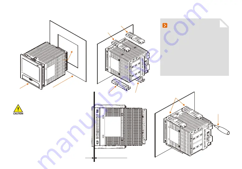
(4) How to attach on the panel mount
*How to install the product
Display
Panel
(Refer to the panel cutting dimension)
Direction
of insertion
Fixing mount right
Fixing mount right
Fixing mount left
Fixing mount left
Fixing mount
Phillips screwdriver
Panel thickness : 2 ~ 7mm
Display
Panel
(Refer to the panel cutting dimension)
Direction
of insertion
Fixing mount right
Fixing mount right
Fixing mount left
Fixing mount left
Fixing mount
Phillips screwdriver
Panel thickness : 2 ~ 7mm
References
▶
Cut the panel to be installed. Refer to the
[1-2(3) Panel cutting dimension]
▶
Insert into the hole from the rear side of the
product as shown in the above figure.
▶
Fix this product using in fixing mount at the
upper/lower part of the product ( As shown
in the figure) Apply 0.2Nm~0.4Nm of torque
in case of assembling the fixing mount
(Use the Phillips driver)
The clamping screw is too tightened, the panel
surface is deformed. It can cause touch not working
normally, or likely to decrease waterproof.
Cautions
Содержание SDR100E Series
Страница 19: ...17 02 Operation and setting Password input screen Screen without DI option Screen with DI option...
Страница 23: ...Main screen Part 03...
Страница 25: ...4 1 Graph recording screen 24 Graph recording setting Part 04...
Страница 36: ...5 1 Graph view 35 5 2 Data searching 36 Graph searching Part 05...
Страница 39: ...Function setting Part 06...
Страница 51: ...Part 08 Setting canned message...
Страница 53: ...Setting reserve operation Part 09...
Страница 64: ...Part 11 Error history display...
Страница 68: ...Part 12 Setting system parameter...
Страница 70: ...13 1 Sensor input screen 69 Screen for setting the sensor input Part 13...
Страница 95: ...DI function and operation Part 16...
Страница 102: ...System initial setting9 Part 18...
Страница 106: ...104 Fig 18 8 Screen setting for sending to SDR100 Upload Fig 18 9 Screen for parameter file selection to send to SDR100...


