background image

IN

OUT

IN

OUT

IN

OUT

IN

OUT

IN

OUT

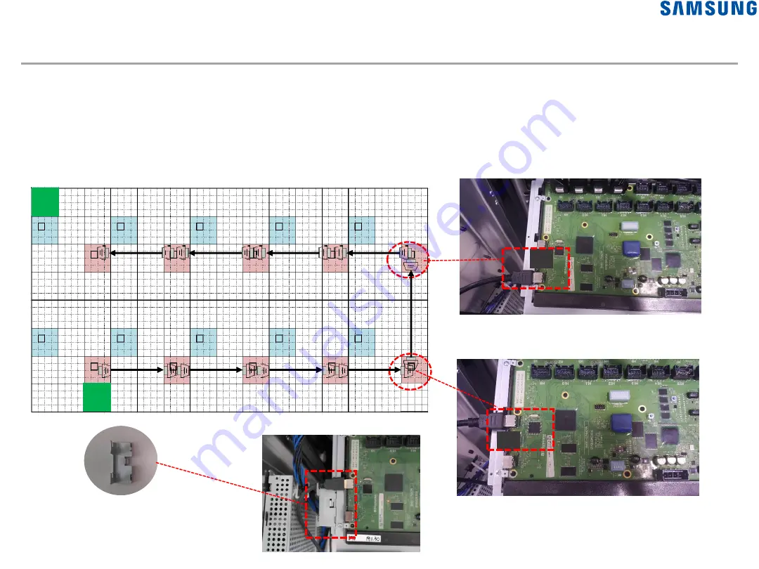
2. Installation : Cable Connections ② Y8 to Y8

55

• Y8 Board to Y8 Board (Backward Connection) 

-

TMDS Cable Connection (VG-XACMBKIT/ENCM)

: For Y8 boards that send data, connect the cables to OUT on the boards. For Y8 boards that receive data, 

connect the cables to IN on the boards, as shown below.

<TMDS cable>

IN

OUT

IN

OUT

IN

OUT

IN

OUT

O

UT

IN

Install the TMDS holder after connecting to 
the input port to prevent damage.

S

S

Содержание XPR Series

Страница 1: ...Outdoor LED Installation Manual XPR Series Standard Cabinet LH080XPRZAS PZ Rev 0 9...

Страница 2: ...guration Fan installation 2 Installation Overview Unboxing Accessary Assembly Fan Assembly Handling Cabinet Mounting Cabinet Y8 Signal B d Assembly Cable Connections Power Connections Waterproof Bezel...

Страница 3: ...ure safety Ensure that the power cord is not close to any heat sources The cord sheath may melt and cause a fire or electric shock Do not install the product in a confined space with poor ventilation...

Страница 4: ...ing object Make sure the LED surface does not face down onto the floor Exercise caution to ensure that the corners of the LED module are not damaged due to contact with external factors Make sure the...

Страница 5: ...ack Uniformity L10 0 15 TBD Video Processing 24 Bit Color Capacity 16 Bit Color Temp 4 500 9 000K Refresh Rate spec 4 800Hz 7 680Hz 7 680Hz 7 680Hz 7 680Hz Horizontal Viewing Angle 160 Vertical Viewin...

Страница 6: ...ack Uniformity L10 0 15 TBD Video Processing 24 Bit Color Capacity 16 Bit Color Temp 4 500 9 000K Refresh Rate spec 4 800Hz 7 680Hz 7 680Hz 7 680Hz 7 680Hz 7 680Hz Horizontal Viewing Angle 160 Vertica...

Страница 7: ...Standard Cabinet Outside 1 Product Information Standard Cabinet 7 Front Rear...

Страница 8: ...Standard Cabinet Product Size 1 Product Information Standard Cabinet 8 Item Spec Cabinet Size W x H 1000 mm x 1000 mm Module Size A x B 250 mm x 250 mm Set depth D 264 3 mm Weight kg 38 kg...

Страница 9: ...Y8 PDS SMPS SMPS SMPS SMPS Standard Cabinet Y8 Product Inside 1 Product Information Standard Cabinet 9 PDS SMPS AC Filter Power In Power Out External Fan position Y8 1 Y8 for 1 block...

Страница 10: ...1 Product Information Package 10 1265 1225 387 Outdoor Cabinet Box Read the label to make sure it is the right cabinet Read the information in the attached label to check the Model Code and Project No...

Страница 11: ...HD and the size covered by the Y8 T con board FHD Zone 15 x 8 Cabinet configuration which is the maximum configuration that can display content with a resolution of FHD or lower Y8 Block 3 x 4 Cabinet...

Страница 12: ...on by screen Signal B d Forward Y8 B d Backward Y8 B d The location depends on the cabinet configuration you want to install See LED configurator This zone configuration differs by pitch Note that the...

Страница 13: ...control unit of System The location of the Redundancy Signal Board is installed in the cabinet where the data ends XPR060 S XPR060 E Cabinet Configuration 12 x 6 Resolution 1920 x 960 of Y8 12 24 for...

Страница 14: ...ion of the Redundancy Signal Board is installed in the cabinet where the data ends XPR160 S XPR160 E Cabinet Configuration 30 x 16 Resolution 1800 x 960 of Y8 12 24 for redundancy of Signal 2 XPR200 E...

Страница 15: ...ocation Fan type 2 External fan Intake Exhaust 1 Internal fan Repeat configuration for 5 Cabinet rows as shown below Intake fan Internal fan Exhaust fan Exhaust fan Intake fan Internal fan External Fa...

Страница 16: ...Y8 Signal B d Assembly Cable Connection Power Connection Control Room Setting Pre Working Before Cabinet Hang Accessories Assembly SW set up Installation Overview The installation follows the below or...

Страница 17: ...EXHAUST FAN EXHAUST FAN Y8 Y8 Redundancy INTAKE FAN INTERNAL FA N INTAKE FAN INTERNAL FAN INTAKE FAN INTERNAL FAN Ex Total Screen 3x4 Cabinet 1 Pre Cabinet Installation Accessories EXHAUST FAN INTAKE...

Страница 18: ...Pre Installation Work All Cabinet Do the following for all cabinets Ex FHD Zone Screen 1 cabinet Work 2 Installation Unboxing Cabinets Accessories...

Страница 19: ...bag Unboxing 2 Installation Unboxing Cabinets Accessories When unboxing the package or moving the product do not hold the handles in the middle of the rear door or the plastic covers on both corners o...

Страница 20: ...cabinet Unboxing 2 Installation Accessory Assembly Attach the Eye Nut x2 to the brackets at both ends on top of the cabinet Screw point Bolt Ring Ring Eye Nut 1 by 1 installation Every cabinets Secti...

Страница 21: ...Installation Pre work on ground lowest cabinets P38 Do the following for lowest cabinets Ex FHD Zone Screen 1 cabinet to work on Bolt M8 L18 Attach the Bracket frame bottom L R to the bottom of the ca...

Страница 22: ...on every 5th lines intake Exhaust P23 P24 Ex FHD Zone Screen 1 cabinet to work on Intake Fan Internal Fan Exhaust Fan Exhaust Fan Intake Fan Internal Fan Install every fifth line but if the screen is...

Страница 23: ...lation 23 2 Installation Fan Assembly Open the doors 1 Remove the PC sheet 3 Insert the filter Install the fan and the filter without separating it 2 Remove the view 5 Attach the PC sheet x4 to the to...

Страница 24: ...an Assembly Open the doors Hook the top of fan on the Bracket support Rear service site Screw M4 L6 1point Front service site Screw M4 L20 2point It depends on whether it is front or rear installation...

Страница 25: ...P20 0 3 1 0 0 3 1 0 0 4 P6 P8 P10 P16 P20 Used tools Kit box Combination wrenches 13mm 21mm Ratchet with deep socket 13mm 21mm Ratchet with deep socket 13mm 21mm 25 When fixing after hanging the cabi...

Страница 26: ...undant wire Maximum number of cabinets that can be moved when installing a section 4x2 cabinets spreader bar Remove the Eye Bolt after hang a cabinet section on the frame Guide to moving the product u...

Страница 27: ...e top and bottom of the two cabinets with bolts C B N C B N Z seam Cabinet to be extended Tighten the two cabinets directly from inside the cabinet with bolts doors open At the same time adjust the Z...

Страница 28: ...cabinet below M8 L18 BOLT Lowest of section Y seam Tighten the two cabinets directly from inside the cabinet with bolts doors open At the same time adjust the Z seam based on the LED modules on the fr...

Страница 29: ...cabinet section Z seam Tighten the two cabinets sections directly from inside the cabinet with bolts doors open At the same time adjust the Z seam based on the LED modules on the front M8 L18 BOLT X s...

Страница 30: ...kets on the cabinet below M8 L18 BOLT Upward extension cabinet section cabinet below M8 BOLT NUT M8 BOLT NUT Upward extension cabinet section Y seam Tighten the two cabinets sections directly from ins...

Страница 31: ...OLT Tighten the three cabinets directly from inside the cabinet with bolts doors open At the same time adjust the Z seam based on the LED modules on the front Tighten the bolts between the bottom of t...

Страница 32: ...OLT NUT M8 BOLT NUT Hang the Brackets of cabinet section corner on the frame Tighten the top every brackets to the L shaped steel assembled on the H beam Tighten the two cabinets sections directly fro...

Страница 33: ...ED modules as shown Y seam M8 L18 BOLT 33 M8 BOLT NUT M8 BOLT NUT Tighten the two cabinets section directly from inside the cabinet with bolts doors open At the same time adjust the Z seam based on th...

Страница 34: ...sed on the cabinet below And disassemble some LED modules as shown Tighten the three cabinets sections directly from inside the cabinet with bolts doors open At the same time adjust the Z seam based o...

Страница 35: ...Assembly Y8 Address Setting Signal B d Assembly Cable Connection Y8 to Module Y8 to Y8 PDS to PDS B d ID setting Signal B d to Y8 PDS Power Connection EXHAUST FAN Signal B d EXHAUST FAN EXHAUST FAN Y...

Страница 36: ...ssembly 36 9 Open the door on the rear of the cabinet and attach the Y8 board Fig 9 Attaching the Y8 board Fig 9 Y8 Board attachment point Bracket Support assembly Y8 assembly sliding Y8 to Bracket th...

Страница 37: ...d give the address so that the system can check the Y8 location Refer to the figure below to specify the location by setting the corresponding binary switch Screen Y8 Board 1 Cabinet Y8 Board 000 001...

Страница 38: ...0 0 0 0 002 00000010 0 1 0 0 0 0 0 0 003 00000011 1 1 0 0 0 0 0 0 004 00000100 0 0 1 0 0 0 0 0 005 00000101 1 0 1 0 0 0 0 0 006 00000110 0 1 1 0 0 0 0 0 007 00000111 1 1 1 0 0 0 0 0 008 00001000 0 0 0...

Страница 39: ...y 39 Attaching the Signal Box Fig 10 Signal Box attachment point screw Attach the Bracket Support Attach the Signal Box sliding Board to Bracket then turn lock Open the door on the rear of the cabinet...

Страница 40: ...0 Signal Board Assembly Cap Cable Gland Snap lock pin Optical repeater point Signal Box attachment point Attach the optical repeater Remove the cap and attach the cable gland to the power cable inlet...

Страница 41: ...he cover after connecting the data cable Fig 13 Data cable specifications It is necessary to add Teflon tape when using a cable with a circular 7 0 8 0mm and 7 0mm or less Data cable Connection Fig 12...

Страница 42: ...the data cable connects the following ports P6 Connect 12 ports of the total 16 ports P6 1 2 3 4 5 6 7 8 9 10 11 12 2 x 3 cabinet Y8 B d 2 Installation Cable Connections Y8 to Module 4 ports are not u...

Страница 43: ...able connects the following ports P8 10 16 20 Connect 16 ports of the total 16 ports 1 2 3 4 5 6 7 8 9 10 11 12 13 14 15 16 2 Installation Cable Connections Y8 to Module 1 2 3 4 5 6 9 10 11 12 13 14 7...

Страница 44: ...Block Configuration Block 3 x 4 Cabinet Y8 Board is able to control upto 12th 3x4 Cabinet Y8 Y8 Y8 Y8 XPR100 S XPR100 E XPR080 S XPR080 E Screen P10 Block Configuration Block 4 x 4 Cabinet is able to...

Страница 45: ...Configuration Block 2 x 4 Cabinet Y8 Board is able to control up to 8th 2x4 Cabinet XPR160 S XPR160 E XPR200 E XPR060 S XPR060 E Screen P16 P20 Block Configuration Block 10 x 4 Cabinet Y8 Board is abl...

Страница 46: ...e Connection 3x4 Cabinet 1 As shown in the figure below the Y8 board VG XACMBKIT for Forward Path is used for the 1 cabinet of the figure below and the Y8 board for Redundant Path Connect the board VG...

Страница 47: ...Y8 P1 P2 P3 P4 P9 P10 P11 P12 P13 P14 P15 P16 No Cable Label P1 P2 P3 P4 P5 P6 P7 P8 P9 P10 P11 P12 P13 P14 P15 P16 Row1 800mm Row2 500mm Row3 800mm Row4 500mm P1 P16 Forward connection data cable la...

Страница 48: ...ion diagram of 3x4 cabinet RP1 to PR16 Redundancy connection data cable label No Description RP1 RP2 RP3 RP4 RP5 RP6 RP7 RP8 RP9 RP10 RP11 RP12 RP13 RP14 RP15 RP16 RP1 RP2 RP3 RP4 RP5 RP6 RP7 RP8 RP9...

Страница 49: ...e cables and to connect data cables between the cabinets Run cables through the waterproof tunnel next to each cabinet Y8 Out in As shown in the picture there is a cabinet in the middle align and conn...

Страница 50: ...ns Y8 to Module 50 Data cable Connection 3x4 Cabinet 3 Caution When securing cables exercise caution to ensure that AC lines do not come into contact with data power cables P5 P6 P7 P8 Y8 P1 P2 P3 P4...

Страница 51: ...RP6 RP7 RP8 RP9 RP11 RP12 RP13 RP14 RP15 RP16 RP10 P5 P6 P7 P8 Y8 P1 P2 P3 P4 P9 P10 P11 P12 P13 P14 P15 P16 Data cable Connection 3x4 Cabinet 4 Use cables to to connect Y8 boards to cabinets redunda...

Страница 52: ...lation Cable Connections Y8 to Module 52 Ex If 4 x 2 is left Ex If 3 x 2 is left Note If the layout of connected cabinets is not 3x4 connect cables based on the condition with the bottommost cabinets...

Страница 53: ...NCM For Y8 boards that send data connect the cables to OUT on the boards For Y8 boards that receive data connect the cables to IN on the boards as shown below TMDS cable OUT IN IN OUT IN OUT IN OUT IN...

Страница 54: ...ction Serial connection RJ45 LAN cable VG XACMBKIT ENCM For Y8 boards that send data connect the cables to TX on the boards For Y8 boards that receive data connect the cables to RX on the boards as sh...

Страница 55: ...TMDS Cable Connection VG XACMBKIT ENCM For Y8 boards that send data connect the cables to OUT on the boards For Y8 boards that receive data connect the cables to IN on the boards as shown below TMDS c...

Страница 56: ...onnection Serial connection RJ45 LAN cable VG XACMBKIT ENCM For Y8 boards that send data connect the cables to TX on the boards For Y8 boards that receive data connect the cables to RX on the boards a...

Страница 57: ...data signals are delivered in a single zone the PDS boards connected to the forward specific signal bracket are connected to half of the cabinets Group1 and the PDS boards connected to the backward sp...

Страница 58: ...1 Serial connection RJ45 LAN Cable connection VG XACP8KIT ENCP For PDS boards that send data connect the cables to OUT on the boards For PDS boards that receive data connect the cables to IN on the bo...

Страница 59: ...rd Group1 Serial connection RJ45 LAN Cable connection For cabinets connected to Group1 connect LAN cables to OUT on the PDS boards that send data and to IN on the PDS boards that receive data as shown...

Страница 60: ...first and last PDS boards and specify the MODE ZONE TACT LED On the first PDS board press the Tact switch once to change the state to RED On the last PDS board press the Tact switch twice to change t...

Страница 61: ...2 Serial connection RJ45 LAN cable connection VG XACP8KIT ENCP For PDS boards that send data connect the cables to OUT on the boards For PDS boards that receive data connect the cables to IN on the bo...

Страница 62: ...rd Group2 Serial connection RJ45 LAN cable connection For cabinets connected to Group1 connect LAN cables to OUT on the PDS boards that send data and to IN on the PDS boards that receive data as shown...

Страница 63: ...first and last PDS boards and specify the MODE ZONE TACT LED On the first PDS board press the Tact switch once to change the state to RED On the last PDS board press the Tact switch twice to change t...

Страница 64: ...Without Signal B d If you do not install Signal B d connect directly from PC box as follows TMDS Cable LAN Cable 1st Y8 Board Notes Serial Server Port Port 1 Y8 connection Port 2 Light Sensor connect...

Страница 65: ...of the first Serial Server TMDS Cable LAN Cable CAT5 to Serial Adapter 1st Y8 Board 1st Y8 Board Signal Boardt Signal Board AC DC Converter Fiber to LAN Power Injector AC DC Converter AC Junction Phoe...

Страница 66: ...o the IN port of the first PDS board Notes Serial Server Port Port 1 Y8 connection Port 2 Light Sensor connection Port 3 PDS connection Serial Server Signal Board AC DC Converter Fiber to LAN Power In...

Страница 67: ...sing LAN cables 1st Y8 Board Light Sensor Signal Board Notes Serial Server Port Port 1 Y8 connection Port 2 Light Sensor connection Port 3 PDS connection Power Injector LAN Cable INPUT OUTPUT Serial S...

Страница 68: ...ng more than the allowed number of power connections the power breaker may be lowered or the product may be damaged due to overcurrent The connection must be below the quantity and we are not responsi...

Страница 69: ...rproof IP68 two way plug https www amazon com FX Junction Waterproof Connector External dp B07FDKH4G3 ref pd_sbs_60_1 130 6739139 1804662 _encoding UTF8 pd_rd_i B07FDKH4G3 pd_rd_r 93be4196 88a4 49eb b...

Страница 70: ...move the cap at the bottom of the back of the cabinet and assemble the cable gland between the power cable connections Fig 7 Power connection Fig 7 Power Data cabling position Cap detachment Cable Gla...

Страница 71: ...e of the cable handle must be assembled in accordance with the connector pin direction In the direction of the arrow on the connector when connecting AC power You have to fit it in You have to push it...

Страница 72: ...1 AC Junction Box No Compone nt type Item type Item name Description Accessory Power cable AC Junction BOX to Cabinet 600mm 3pin 20A AC IN only Accessory Power cable Cabinet to Cabinet 1100mm 3pin 20...

Страница 73: ...nets does not exceed four 1 2 3 4 The connections 1 and 5 in the distribution unit are located outside the cabinet connecting to inside cabinet 5 6 7 8 Breaker Specification 30A D Type No Component ty...

Страница 74: ...ot exceeded Single cabinet power for P8 1000 W 1 2 3 4 5 6 7 8 Breaker Specification 30A D Type No Component type Item name Description Accessory Power cable AC Junction Box to Cabinet 600mm 3pin 20A...

Страница 75: ...4 15 16 No Component type Item name Description Accessory Power cable AC Junction Box to Cabinet 600mm 3pin 20A AC IN only Accessory Power cable Cabinet to Cabinet 1100mm 3pin 20A Both AC IN OUT The c...

Страница 76: ...doors PDS board Rear of caninet view Internal Fan Connect the Fan cable in the KIT BOX like these pictures Intake Fan Exhaust Fan Internal Fan Power is from upper cabinet PDS In the case of a cabinet...

Страница 77: ...p rubber Cover Cap plastic Cover Fan Top Cover Fan Bottom PC Cap Sheet PC Bot Sheet PC Handle Sheet Waterproof Accessories Assembly This is the last step in the cabinet installation and install the fo...

Страница 78: ...ion Add accessory quantities to the corner cabinet Waterproof Accessories Assembly This is the last step in the cabinet installation and install the following accessories on the outermost face of the...

Страница 79: ...ap plastic Cover Fan Top Cover Fan Bottom PC Cap Sheet PC Bot Sheet PC Bot Sheet Attach sheets to the cabinet from inside The 4 snaps should be assembled Remove sheet Attach the sheet to the location...

Страница 80: ...d disassemble if other caps are assembled Stick it completely 45 45 Disassemble Rear service Open the doors Front service Disassemble the LED modules for front 80 Attach its from the outside Remove sh...

Страница 81: ...les 2 Installation Waterproof Accessories Assembly SCREW M4 L12 rubber BN81 19153A Place it on top of the cabinet from outside to fit the left and right The dug side is left and right Cover Cap rubber...

Страница 82: ...over Cap plastic Cover Fan Top Cover Fan Bottom PC Cap Sheet PC Bot Sheet PC handle Sheet 82 PC Handle Sheet Attach it to the cabinet handle from the outside 2 Installation Waterproof Accessories Asse...

Страница 83: ...ach side of the cabinet are See illustration on right as different 83 Attaching protection frames for the outer cabinets on the screen 2 Installation Protect Frame Assembly Optional Aluminum Black ano...

Страница 84: ...align it along front surface 4 Keep Frame Bottom flat by pushing up the center area 5 Assembly Frame Bottom to cabinets by 2EA M8L12 Bolt 6 Locate the Cabinet that needed to install Frame Top 7 Attach...

Страница 85: ...t that needed to install Frame Left or Right 2 Assemble Stud pem to that cabinet 3 Attached Frame Left Right to cabinet align it along front surface 4 Assembly Frame Bottom to cabinets by 2EA M4L12 sc...

Страница 86: ...ion Ex 2x2 cabinet M4L6 1 Install Cover Frame Top Bottom from left to right 2 Install Cover Frame Left Right from bottom to top 3 Use 2EA M4L6 screw to connect between Cover Frame 2 Installation Prote...

Страница 87: ...M4 screw Frame Top Bottom at right end Frame Left Right at top end 2 Assemble Bracket Corner to it designed position 3 Fasten M4L6 screw between Bracket Corner and Frame Left Right 4 Fasten M4L12 scr...

Страница 88: ...stallation tool Combination wrenches 13mm 21mm Ratchet with deep socket 13mm 21mm Level Cordless Drill With 2 Phillips bit 2 Phillips screw driver Flat Head screw driver 10 25mm Adjustable wrench Part...

Страница 89: ...oose one VG XACNBKIT EN Control Main P16 20 VG XABS8KIT EN BRACKET Frame Kit Essential VG XAFN8KIT EN FAN ASSY plastic filter fan Essential VG XACP8KIT EN Power Cable Misc Essential VG XACSBKIT EN Con...

Страница 90: ...517A BRACKET FRAME BOTTOM LEFT 8EA BN61 16554A BRACKET FRAME BOTTOM RIGHT 8EA BN61 16555A COVER BOTTOM 32EA BN81 19514A COVER TOP 32EA BN81 19513A Bolt M8 L18 32EA BN81 19153A Hex Bolt M8 L30 20EA BN8...

Страница 91: ...VG XAFAHKIT per 1 set INTAKE FAN 2EA BN81 19505A SCREW M4 L6 4EA BN81 19151A SCREW M4 L20 4EA BN81 19152A EXTERNAL FAN CABLE 1EA BN39 02521A EXHAUST FAN 2EA BN81 19506A FILTER 4EA BN63 19239A INTENAL...

Страница 92: ...t SCREW M4 L6 3EA BN81 19151A Y8 CONTROL BOARD 1EA BN41 02796A BRACKET SUPPORT 1EA BN61 16680A TMDS HOLDER 1EA BN81 19168A TMDS CABLE 5M 1EA BN81 19536A Assy DATA CABLE 5EA per code 4 Cables BN82 0254...

Страница 93: ...1EA BN41 02796A BRACKET SUPPORT 1EA BN61 16680A TMDS HOLDER 1EA BN81 19168A TMDS CABLE 11M 1EA BN81 18713A Assy DATA CABLE 5EA per code 4 Cables BN82 02546A BN82 02547A BN82 02548A BN82 02552A BN82 0...

Страница 94: ...EA BN41 02796A BRACKET SUPPORT 1EA BN61 16680A TMDS HOLDER 1EA BN81 19168A TMDS CABLE 5M 1EA BN81 19536A Assy DATA CABLE 5EA per code 4 Cables BN82 02549A BN82 02550A BN82 02551A BN82 02554A BN82 0255...

Страница 95: ...A BN41 02796A BRACKET SUPPORT 1EA BN61 16680A TMDS HOLDER 1EA BN81 19168A TMDS CABLE 11M 1EA BN81 18713A Assy DATA CABLE 5EA per code 4 Cables BN82 02549A BN82 02550A BN82 02551A BN82 02554A BN82 0255...

Страница 96: ...ASTER POWER CABLE 2EA BN39 02536A LAN CABLE 8EA BN81 18712A DATA CABLE 8 8EA BN82 02556A BN82 02557A CAP PC SHEET 8EA BN81 19162A COVER CAP 8EA BN63 18341A BN63 18398A HANDLE PC SHEET 4EA BN81 19164A...

Страница 97: ...A COVER FRAME RIGHT 4EA BN81 19509A GUIDE PIN 8EA BN81 19171A L BRACKET 10EA BN81 19522A M8 BOLT NUT 16EA BN81 19158A BACKET CORNER BOT LEFT 1EA BN81 19512A BACKET CORNER BOT RIGHT 1EA BN81 19512A BAC...

Страница 98: ...rate purchase item 3 Accessory Kit 98 Protection Frame VG XAFH4KIT per 1 set COVER FRAME BOT 4EA BN81 19511A COVER FRAME TOP 4EA BN81 19510A Bolt M8 L35 8EA BN81 19172A Bolt M8 L12 8EA BN81 19173A SCR...

Страница 99: ...ory VG XASBKIT per 1 set 5 volt PSU BN81 17909A 12 volt PSU BN81 17910A LAN Cable Serial Server 1EA BN81 19180A 3M Fiber Jumper 2EA BN81 13643A Serial Adapter 4EA BN81 13912A HDMI Fiber Receiver 1EA B...

Страница 100: ...ial Server 1EA BN81 19180A 3M Fiber Jumper 2EA BN81 13643A 5 volt PSU 1EA BN81 17909A Serial Adapter 4EA BN81 13912A 12 volt PSU 1EA BN81 17910A LAN Cable 1M Fiber Jumper 2EA BN81 13642A Fiber Enclosu...

Страница 101: ...Base AGS PC 1EA BN81 17540A DisplayPort to VGA 1EA BN81 13793A Monitor 7 1EA BN81 13838A Windows 10 LTSB 1EA BN81 15702A Power Injector 1EA BN94 13069A 12 volt PSU BN81 17910A LAN Cable RJ45 to DB9 Se...

Страница 102: ...Control room This refers to a room where you can control and monitor the screen when installing a sports space or a large outdoor screen If control room is provided installation can be done using Sig...

Страница 103: ...Control PC Internet 4k Media Player Data Path Y8 Board Power Distribution LED SCREEN Control Room TMDS MC Fiber MC TMDS MC Fiber MC Signal Bd TMDS MC Fiber MC TMDS MC Fiber MC TMDS Cable LAN Cable Opt...

Страница 104: ...tting System Configuration Without Control room 104 Total system configuration Without Control room LED Control PC Internet Y8 Board LED SCREEN PC BOX TMDS Cable LAN Cable Power Cable Serial Server Po...

Страница 105: ...rol room LED SCREEN LED Control PC Internet Y8 Board LED SCREEN PC BOX TMDS Cable LAN Cable Power Cable Power Distribution LED Control PC LCD Monotor PDS Board Y8 Board PDS Board HDMI Distributor LAN...

Страница 106: ...he System Matrix PV System and Processor Please contact SI for further information regarding use and connection LED Control PC Internet 4k Media Player Data Path TMDS MC FBR MC TMDS MC FBR MC ETH1 ETH...

Страница 107: ...rol PC to enable a connection with the Serial Server Next in the Internet Explorer address bar enter the Serial Server IP address to access the settings screen Click the Login button You do not need t...

Страница 108: ...8 Serial Server Setting Configure settings for each port ports 1 to 4 as shown below Mode RS 422 4 wire Baud Rate 115200 Press Save The Serial Server automatically reboots The reboot process takes abo...

Страница 109: ...isplays With this software you can control multiple displays of different sizes and pixel pitches Use the Setup System Matrix 20 04 0802x64 msi file to install the System Matrix software After the sof...

Страница 110: ...110 System Matrix program setting Set the value for the XPR model on the Settings Output Settings screen of the main screen When connecting to Redundant Y8 board Choose Dual Interface and change the R...

Страница 111: ...on set Country Region City to suit the installation location Normally set to automatically adjust the brightness according to the Sunrise Sunset time Latitude Longitude is automatically specified acco...

Страница 112: ...4 Control Room Setting System Matrix 112 System Matrix program setting Add the Controllers and Displays you want to control from the menu Manage Systems at the top of the main screen...

Страница 113: ...Connect the added controller and display to each other Click and drag the mouse over the Display Area while you click on the appropriate Controller Area After confirmation of link click Save Exit Con...

Страница 114: ...4 Control Room Setting System Matrix System Matrix program setting The Controller window appears and for detailed setup click the Setting button 114...

Страница 115: ...Setting System Matrix 115 System Matrix program setting Click the configure output layout button the Layout button to set the value for the associated screen layout example Configure 2x2 Cabinet scre...

Страница 116: ...rix 116 Number of connected PDS Master Y8 Redundant Y8 Light Sensor PDS System Matrix program setting On the Communications Settings screen enter the Serial Server connection information Connected Ser...

Страница 117: ...creen output control simple screen brightness control Use for troubleshooting purposes such as print test pattern and video signal color uniformity etc Schedule the video contents Power supply status...

Страница 118: ...General Output Output Enter the desired default brightness value as a percentage in the General Output field at the top center of the window The display brightness is set to this setting when the pro...

Страница 119: ...ing the Light Sensor and entering the Day Lumens Night Lumens value When enabled the light sensor automatically controls the brightness Use Global Sensor If you check this function you can adjust the...

Страница 120: ...mum brightness value of the desired display to Min Set the minimum brightness value for the desired display to If you want to use Dynamic brightness mini max level you should check Use ramping box 2 D...

Страница 121: ...fter checking Enable press the right button to modify the Dimming Schedule file The Dimming Schedule is created as a text file based on HTML code After modification the Save Exit button must be presse...

Страница 122: ...4 Control Room Setting System Matrix 122 1 2 3 System Matrix basic function Global Control Serial Colors Global Settings Diagnostics 4...

Страница 123: ...ndow 2 Blank Output Click the Disable Output button in the Global Control window to stop the image output signal To print the image again click the Enable Output button Blanking This function allows y...

Страница 124: ...rightness of the display to the desired value When the program restarts the Display will return to the default brightness setting 4 Brightness Adjustment Use the Brightness slider bar to control globa...

Страница 125: ...programwindow 2 Serial Color Test Patterns output The left side of the Serial Color Control window displays a list of connected devices The checkbox allows you to output a specific pattern on the sele...

Страница 126: ...System Matrix basic function Global Setting Blanking Schedule The function allows you to stop the display output at the specified time zone between the first and second designated time This feature s...

Страница 127: ...able monitoring and diagnosis of product status Data about the power supply status each pixel module Y8 status and PDS diagnostic functions are displayed and the temperature of the product can also be...

Страница 128: ...4 Control Room Setting System Matrix 128 System Matrix basic function Diagnostics Module...

Страница 129: ...om Setting System Matrix 129 System Matrix basic function Diagnostics Check the Module F W Version Check the Y8 F W Version Check the Module Temperature When you check Show problems detail information...

Страница 130: ...4 Control Room Setting System Matrix 130 System Matrix basic function Power Status PDS diagnostics 1 PDS Diagnostics function Double click on the Power Status area of the System Matrix main window...

Страница 131: ...131 System Matrix basic function Power Status PDS Diagnostics You can monitor ID F W version FAN status temperature Y8 module status of PDS and perform FAN on off Y8 on off module on off and F W updat...

Страница 132: ...etting System Matrix 132 System Matrix basic function Power Status PDS Control 2 PDS Control function Commands You can select Fan Control to adjust Top Rear Fan On Off and Speed Stage 2 Fan Speed Adju...

Страница 133: ...tion Power Status PDS Control 2 PDS Control function Commands You can select Auto Manual mode by selecting Control Mode Auto Mode for automatically adjusting Fan speed according to reference temperatu...

Страница 134: ...Control Room Setting System Matrix 134 System Matrix basic function Power Status PDS Control 2 PDS Control Function Commands You can update the PDS firmware by selecting Update Firmware L XPRMWWAC sre...

Отзывы: