background image

Samsung Electronics

3. Preparation for Cabinet Installation

◈ Reference : Process of Screen check

26

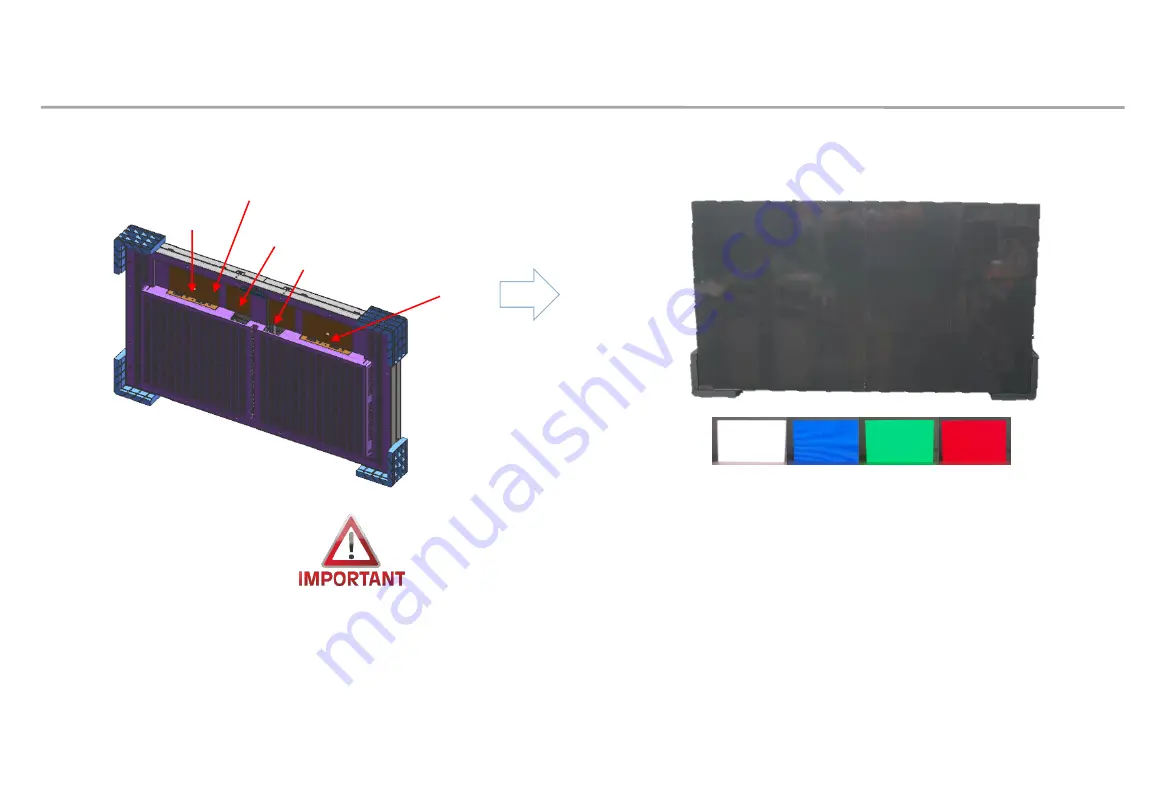
화면 검사 사진 확인

Check the picture of the screen 

Internal white pattern

1. After turn on power, press the toggle switch button for five seconds

2. Dehumidification screen comes out, push the toggle switch twice

3. when the white screen is displayed, check the defective LED by sequentially pressing toggle switch 

* Do not turn on the white pattern over 10 seconds before dehumidification

4. if you need more brighter pattern, push ‘toggle switch’ button for three(3) seconds in white pattern

5. push toggle switch for three(3) seconds again to exit factory OSD

POWER INLET

POWER OUTLET

SWITCH

TOGGLE SWITCH

TOGGLE SWITCH

Содержание SNOW-1810U

Страница 1: ...Samsung Electronics LED Display Installation Manual LH008IWJ P0 84 LH012IWJ P1 26 LH016IWJ P1 68 SNOW 1810U Ver 2 0 2020 03 20 ...

Страница 2: ...Samsung Electronics Revision History 1 Version Date Y M D Description 2 0 2020 03 20 New Release ...

Страница 3: ...r Operation condition from User manual Case when period between unpacking and turning on the power of products is spent more than 7days even though it is under Samsung recommended storage condition Case when production date on the label is exceed more than 6 months even though vacuum packaging is no problem When Volatile chemicals such as oil paint solvent are used or operation condition is exceed...

Страница 4: ...environment condition is under operation condition When environment condition is exceed operation condition products are out of warranty Please check environment condition Even products are operating if the installed place have extra construction such as interior modification MUST do dehumidification following installation condition It is possible to happen dew condensation on surface of products ...

Страница 5: ... possible to happen when surface of products is colder than environment temperature or hot humid air blow to cooled surface of products cf Principle of happening dew on surface of glass which have ice Case when dew condensation is happen on products it is possible to be the root of defect In this case it is possible to be out of warranty ...

Страница 6: ... check same firmware of model marked red letter in below upper number of version marked blue in below You can update firmware through LSM Please refer 7 1 PC control program for the way to update firmware 5 Guidance of latest firmware Cabinet Main L xxxMWWAC nnnn n xxx Pan name nnnn n version FPGA aabbb_ddddd aa pixel pitch bbb LED package type ddddd version Example IER P2 5 Cabinet L IERMWWAC 100...

Страница 7: ...se the cable above CAT6 STP FTP level Length 15m 100m Do not use comb or pinstripe cable CAT6 UTP can not be allowed All Power cables and OCM cable must be connected firmly Do not mix cabinet which have different Project number each cabinet have its own project number Module Cabinet Box ...

Страница 8: ...heck below Cabinet and S box compatibility table information S Box SNOW 1810U SNOW 1703ULD SNOW 1703U I G BN91 20525A BN91 19993A BN91 19100A Cabinet IF015H IF020H IF025H IF025H D IF040H D IF060H D IF012J IW008J IW012J IW016J IF015H IF020H IF025H IF025H D IF040H D IF060H D IF012J IF015H IF020H IF025H IF025H D IF040H D IF060H D ...

Страница 9: ...n for Cabinet Installation 15 page 4 Frame Installation 22 page 5 Cabinet Frame Installation 30 page 6 Disassembly Front Service 41 page 7 Cable Connection 58 page 8 S BOX Installation and Connection 71 page 9 LSM Settings and How to Use 88 page 10 Issue and Solution 103 page 11 Color Calibration 104 page 12 Bezel Installation 107 page 13 Annex 115 page 8 ...

Страница 10: ...it 1400 nit 1000 nit Contrast Ratio 10 000 1 Viewing angle H V 145 155 140 160 135 155 Refresh rate 1920 Hz 3840 Hz Power Spec Input Power 100 240 VAC 50 60 Hz Power consumption Max 190 W Cabinet 192 W Cabinet 180 W Cabinet Operation Spec Working Temperature 0 40 10 80 RH IP Rating IP20 Power Daisy Chain 220V 110V 4sets 3sets Certification Spec Safety 60950 1 EMC Class B 1 Product Information and ...

Страница 11: ... 151 2 mm Weight 12 5kg 12 2kg 12 5kg Screen FHD Cabinet Q ty 2x2 4set 3x3 9set 4x4 16set I G Q ty 1 1 1 Size 1612 8mm X 907 2mm 2419 2mm X 1360 8mm 3225 6mm X 1814 4mm Frame Kit VG LFJ08FWW VG LFJ08TWW VG LFJ08UWW Bezel IWJPA WP008D2X2 IWJPA WP008D3X3 IWJPA WP008D4X4 UHD Cabinet Q ty 4x4 16set 6x6 36set 8x8 64set I G Q ty 4 4 4 Size 3225 6mm X 1814 4mm 4838 4mm X 2721 6mm 6451 2mm X 3628 8mm Fram...

Страница 12: ...eware not to touch LED screen with bare hands without putting gloves on Beware of LED Film Damage due to Metallic Substances Beware not to have metallic substances pulled in to the surface due to the magnetic force on the front side of the LED If any metallic substances get drawn in on the surface please disassemble the module and then remove the pollutants by using a magnet Beware of LED Damage d...

Страница 13: ...he glass detergent directly on the screen Hard stuff on screen surface can damage LED chip and film during cleaning Clear screen surface before cleaning Watch out for damage when cleaning gap between Half Cabinets Watch out for damage when cleaning gap between Modules Do not insert any cleaning tool or spay cleaner directly into the gap Do not wipe the LED surface with hard materials such as paper...

Страница 14: ...nt tool BN81 17112A GAP TOOL BN81 17113A Glove RA00400E 002539 Hex Wrench 2mm 6mm PLIER BN81 17541A Provided in Frame Kit VG LFJ08 WW Provided in accessory kit CY WJJPWP PROTECTION BN81 17111A EDGE PROTECTION V H BN81 17514A BN81 17515A Provided in Frame Kit BN96 48298A Cover PCB BN63 18008A SCREW MACHINE HOLDER SCREW BN61 16452B Packed in a small zipper bag M4 L6 M3 L6 ...

Страница 15: ...ne except for the noon time zone during work is allowed If surface temperature rise is minor 1 2 degrees allowed Use UV blocking light blocking film when installation of window adjacent is inevitable Room temperature is recommended to be 0 25 Effect of Cold Hot Wind on Air Conditioning System If the cold or hot air is the same air conditioning system be careful not to affect the product Air temper...

Страница 16: ... screen installation 10 Recommended condition Min 500mm set ceiling Min 100mm when maintaining the indoor temperature below 25 degrees due to air conditioning operation Air vent area Must use mesh with an opening rate of 60 or more Air vent area Must use mesh with an opening rate of 60 or more At least 60mm installation space required for upper lower left and right All interior finishes proceed af...

Страница 17: ...installation Air vent area WALL Min 100mm set floor 11 Recommended condition Min 500mm set ceiling Min 100mm when maintaining the indoor temperature below 25 degrees due to air conditioning operation 2 Check Point about the Radiant Heat without Fan ...

Страница 18: ... vent area must use mesh with an opening rate of 60 or more Air vent area Must use mesh with an opening rate of 60 or more Min 60mm 2 Check Point about the Radiant Heat with Fan Vent and interior finishing work will proceed after screen installation Recommended condition Min 500mm set ceiling Min 100mm when maintaining the indoor temperature below 25 degrees due to air conditioning operation ...

Страница 19: ...eat with Fan Vent and interior finishing work will proceed after screen installation left and right sealing Excluding FAN should be sealed Air vent area must use mesh with an opening rate of 60 or more Recommended condition Min 500mm set ceiling Min 100mm when maintaining the indoor temperature below 25 degrees due to air conditioning operation ...

Страница 20: ...back of the wall WALL Min 60mm Min 100mm set floor 14 2 Check Point about the Radiant Heat with Fan Vent and interior finishing work will proceed after screen installation Recommended condition Min 500mm set ceiling Min 100mm when maintaining the indoor temperature below 25 degrees due to air conditioning operation Air vent area Must use mesh with an opening rate of 60 or more ...

Страница 21: ...ox Fig 2 Remove the Top Cushion and hold the handle inside PE Bag and pull out the set then remove PE bag Fig 2 Check whether there is any abnormality on the screen by connecting the power cable Fig 3 Process of Screen check Page 21 Fig 1 Packing Product Fig 2 Remove Al Bag Fig 3 Check the Screen HANDLE BOX CUSHION TOP CUSHION BOTTOM LED SET SWITCH Al Bag ...

Страница 22: ...ached to the top bottom left right Fig 4 Holder PCB Cover PCB Protective Sheet Removal X18 X4 HOLDER PCB COVER PCB Filament Tape 21 Remove Cover PCB and screws and keep them separately It is required when working on the back The Cover PCB Screw and Bolt are included in the accessory of the Cabinet SCREW MACHINE 6003 000133 M4 L8 SCREW MACHINE 6003 001501 M3 L6 ...

Страница 23: ... Cabinet Installation 22 Unfasten the 4 screws on the Cover Corner area to separate those screws and Remove the protective sheet attached to the two sides Top Bottom Fig 4 Fig 4 Cover Corner Removal SCREW SCREW MACHINE 6003 000133 M4L8 X4 ...

Страница 24: ...he module and the Bracket Sub using a gap gauge If the step is 0 06mm or more attach Spacer PET 0 05t 0 1t 23 Step compensation by attaching Gap Sheet Fig 5 Check the difference between the module and B SUB Using Gap gauge Spacer PET In order to minimize the load applied to the module during large size installation Attach it to the Bracket Sub to minimize the gap between the module and the Bracket...

Страница 25: ...ess the button for 3 seconds after the cabinet is turned on When the initial AC power is turned on time required for operation of AM3352 IC is required Wait about 30 seconds and let it go When the button is released Dehumidifying Mode is executed Display the module at the top left Aging with 24 hours on 3초 Aging 24 hours SWITCH Caution The normal installation mode of operating IWJ LH008IWJMWS LH01...

Страница 26: ...ale 8 2 hr 3 Lighting up display with 30 gray scale 10 2 hr 4 Lighting up display with 40 gray scale 15 2 hr 5 Lighting up display with 50 gray scale 20 2 hr 6 Lighting up display with 70 gray scale 25 2 hr 7 Lighting up display with 90 gray scale 35 2 hr 8 Lighting up display with 120 gray scale 45 2 hr 9 Lighting up display with 150 gray scale 60 2 hr 10 Lighting up display with 180 gray scale 7...

Страница 27: ...tion screen comes out push the toggle switch twice 3 when the white screen is displayed check the defective LED by sequentially pressing toggle switch Do not turn on the white pattern over 10 seconds before dehumidification 4 if you need more brighter pattern push toggle switch button for three 3 seconds in white pattern 5 push toggle switch for three 3 seconds again to exit factory OSD POWER INLE...

Страница 28: ...ts ⓐ BRACKET H horizontal 2 2 2 6 ⓑ BRACKET SIDE vertical 2 2 2 2 ⓒ BRACKET MIDDLE vertical 2 3 4 ⓓ JOINT H 2 2 2 3 ⓔ JOINT V 2 4 6 8 ⓕ BRACKET JIG 1 1 1 1 ⓖ LEVELER 2 2 2 ⓗ SCREW 4 6 6 15 ⓘ Anchor 4 6 6 15 ⓙ DRY WALL SCREW 4 6 6 15 ⓚ MANUAL INSTALL 1 1 1 1 ⓛ ALIGN JIG 1 1 ⓜ LEVEL 1 1 2 ⓝ HOLDER PCB 15 30 45 60 Installation Screen Size mm 806 4x453 6 1612 8x907 2 2419 2 1360 8 3225 6 1814 4 ⓝ ...

Страница 29: ... Bracket H Fig 1 Second put 3 groups of Bracket H on ground And insert Bracket Side Middle to Bracket H Fig 2 ⓑ Bracket Side used at side position ⓒ Bracket Middle used at middle position Then fasten up the screws Fig 3 28 Fig 1 Insert Bracket H Fig 2 Insert Bracket V to Bracket H Fig 3 Fix Bracket with screw M4L8 M6L8 ⓐ ⓑ ⓒ ⓑ ⓒ ⓐ ⓐ ...

Страница 30: ...ronics 4 Frame Installation Assemble Leveler on the Bracket Side at required height position Put Leveler on Bracket side at required height position with moving up and down Fig 1 29 Fig 1 Assemble Leveler M4L8 Screw ...

Страница 31: ... frame to the wall use the 6mm hexagonal wrench to correct the gap with the leveling bolt Fig 2 If the leveling bolt is not enough to attach to the wall add Tape Wash to reinforce it Fig 3 In the above way make sure that the frame does not follow the flat wall 30 Fig 1 Make horizontal and Fasten 1point Fig 2 Adjust leveling bolt 1Pt Fastening Adjustment level Leveling Bolt Max 2mm Fig 3 Attachment...

Страница 32: ... fastened according to the guide below Fig 3 Fix the fastening position closest to the bracket side lid among the fastening holes of the bracket H Additional screws may be required depending on the wall status After the wall is fastened remove the leveler 31 Fig 3 Fix Frame with screw Concrete Wall Wood Stud Wall ...

Страница 33: ...Samsung Electronics 4 Frame Installation Precautions for Fastening the Screws 32 ...

Страница 34: ...t Frame Installation to Horizontal Vertical Assemble Joint C Joint V into second assembled Frame 33 Horizontal Extension M4L8 Fastening M4L8 Fastening Vertical Extension Insert the second FRAME to first FRAME Vertical Extension Horizontal Extension ...

Страница 35: ...ertical direction The joints of the frames to be extended are inserted into the existing frames and the jig is inserted to correct position After the Jig fastening fasten the screws between the frames 34 Vertical Extension Horizontal Extension M4L8 Fastening M4L8 Fastening ...

Страница 36: ... fasten the screws Fig 2 In the future service I G must be able to be released through the cabinet and must be installed in the corresponding location Depending on the screen size I G can be placed outside the screen for convenience of work 50 55mm I G Fix I G Location Fig1 Location to Fix the I G and Order of OCM cable Fig2 Location to Fix I G 120 125mm 35 2x2 FHD IW008J 3x3 FHD IW012J 4x4 FHD IW...

Страница 37: ...of the cravings to be closer to the Frame Fig 2 Press the upper side of the Frame and assemble so that it slides towards downward Fig 3 Cabinet Installation 36 Fig 1 Installation sequence of the Cabinet Sliding Screw Fig 2 Adjust the corners to guide line Guide line Guide line Fig 3 Sliding cabinet to Frame 8 7 6 5 16 15 14 13 24 23 22 21 32 31 30 29 40 39 38 37 4 12 21 28 36 48 47 46 45 44 3 11 1...

Страница 38: ...nstalling the I G install the cabinet from the end of the first floor Fig 3 1 Install the Align Jig and fasten the screw after attaching it to the cabinet Fig 3 2 Cabinet Installation 37 37 Fig 3 1 Cabinet Installation Fig 3 2 Screw fastening Fastening M4 L8 ...

Страница 39: ...in the same way as the first stage installation method Fig 5 Install the 3 and 4 steps in the same order Fig 6 After installing each unit make sure that the switch on the back of the cabinet is in the STB mode Cabinet Installation 38 38 Fig 4 Installing the first stage of the Cabinet Fig 5 Fasten the screw with Align jig when installing the 2nd stage of the Cabinet Fig 6 Installing of the 3th and ...

Страница 40: ...on jig V to the corner Fig 1 Push the module and of the cabinet to be installed in the opposite direction Be careful not to collide with the modules Slide the cabinet as shown in Fig 2 When pushing the module push the metal material on the side and be careful not to touch the front module 39 39 Fig 2 Installing 2nd stage of the cabinets Fig 1 Attachment the edge protection Jig Cabinet Installation...

Страница 41: ...ction Jig H and the Edge Protection Jig V Fig 3 Push the module and of the cabinet to be installed in the opposite direction Be careful not to collide with the modules Slide the cabinet as shown in Fig 4 The remaining 3 and 4 stages are also installed in the same way 40 40 Fig 4 Installation of the 2nd cabinet in the 2nd stage Figure 3 Attaching H V for Edge Protection during 2nd Stage Installatio...

Страница 42: ...he Half Cabette to check if there is a difference If the necessary part is the outer part turn the exposed sawtooth to adjust the step If the internal part of Half Cabinet needs adjustment move left and right to secure space for adjustment Up left and right 2mm can be moved between each half cabinet Adjust the step by turning the sawtooth using the step control jig It is possible to flow 1mm in on...

Страница 43: ...ol Turn Gap Tool 90degree 4 Insert Adjusment Tool Turn Holder Magnet 5 Hold Module by Hand Turn Gap Tool 90degree Remove Gap Tool Check Flatness Repeat process if needed 2 0mm 2mm 90 1 Attach Suction Pad counter clockwise module move forward clockwise module move backward Turn Holder 360 Module move 1 0mm Un Lock Lock 90 ...

Страница 44: ...gnment Assemble the cover PCB at the bottom of the cabinet after the first row cabinet installation After assembling the Cover PCB tighten the braid bolts to align the module pixels After installing each unit make sure that the switch on the back of the cabinet is in the STB mode Cover PCB M3L6 M4L6 Cover PCB ...

Страница 45: ...the screen M4L5 tanning bolts are assembled only 1 2mm and later Additional tightening during alignment operation After assembling the Cover PCB fasten the bandbolt from the left and right to work so that the vertical alignment between the central reference pixels is correct To meet the horizontal alignment of the central standard slowly fasten the lowest tanning bolts After the alignment operatio...

Страница 46: ...lignment work using Cover PCB and install it Assemble the holder PCB on the outer surface of the screen Fasten using the M4L6 dish head bolt Install one Holder PCB on the outer surface of all modules located on the outskirts of the top Align modules in X Y direction 45 45 Fig 2 Holder PCB position each set Fig 1 HOLDER PCB Assemby Horizontal center line Vertical center line M4L6 Holder PCB ...

Страница 47: ...tronics 6 Disassembly Front Service Remove bezel and remove Cover Holder PCB GAP SHEET M3L6 M4L6 Horizontal center line Vertical center line Remove bezel and Cover Holder PCB Remove bezel M4L6 Cover PCB Holder PCB ...

Страница 48: ...binet front side LED side to prevent damage to LED Modules while assembly disassembly moving half cabinets X grasp as direction of push or pull Caution Absorber must not be attached across the Module line Handle should be locked in vertical Lock Un Lock Location can be change according to the direction to move Half cabinet 47 Move right Move left Move up Move down ...

Страница 49: ...et locking from center of module to corner 3 Raise the jig vertically and carefully touch module It makes Tak sound when it s done MAGNET JIG model name CY WJJPWP N MAGNET Caution Cannot use Magnet JIG of other LED display model weak magnetic force Use proper Magnet JIG matching with specification Magnet Lock location Caution Be careful not to damage module 48 ...

Страница 50: ...binet Repairing Half Cabinet Dissembled first before taking out repairing half cabinet Based on the Half Cabinets to be replaced the Half cabinets on the left right and top should be pushed outward Edge Protection is needed Refer to the Next In case of bottom line cabinet right upper side of half cabinet should be disassembled with method of and cut off everything ...

Страница 51: ...should be removed pushing order is important Follow the numbers on left picture Use absorbers when you push to keep module from damaged 1 2 3 UHD screen 16Cabinet 32 half cabinet Repairing Half cabinet Push cabinet to upper side to get 2mm gap that located right above repairing Half cabinet Hold it until next step Cover PCB should be removed Use absorbers when you push to keep module from damaged ...

Страница 52: ...e of half cabinet to fix gap You have to lift repairing half cabinet to insert GAP Tool at bottom edge Attach edge protection to repairing half cabinet and remove GAP Tool Edge protection has room for GAP Tool Edge Protection There is module protection blade on the edge Attach it with blade inserted into the gap A S ASSY COVER PROTECTION BN81 17111A Edge Protection 6 Disassembly Front Service ...

Страница 53: ...rotection attached for assembly of the new Half Cabinet For power cable press side locking on both side of connector with PLIER JIG Daisy Chain FFC Cable Redundancy Power Cable SMPS Power Cable Cables need to be removed 4 kinds OCM Cable S M Caution Be careful not to damage connector pin when remove Cable Be careful not to damage cabinet next to Caution Do not apart Half cabinet too far Cable can ...

Страница 54: ...ion Be careful not to damage connector pin when remove Cable Be careful not to damage cabinet next to A S ASSY PLIER JIG There is a groove that takes locking on the top head Locking can slip if it does not get to the groove correctly Fix the JIG to take entire side lock wrong case only clipping end of side lock 6 Disassembly Front Service ...

Страница 55: ...binet with into the edge protection and lock with magnet jig Pull out edge protection after locked Push back moved Half cabinets and assemble Cover PCB and bezel Changing to new Half Cabinet Location of magnet locking Remove absorbers and edge protection LED MODULE BRACKET SUB New cabinet must be changed after conduct Dehumidifying mode Aging Refer to page 100 Caution Be careful not to damage modu...

Страница 56: ...crew Remove Cover Terminal first since this screw Point is concealed Cover terminal Screw point Screw point 6 1 FFC Cable 6 or 7 Power Cable 6 Note that Master Cover terminal has switch on it SCREW MACHINE 6001 003016 M3 L5 SCREW MACHINE 6001 002755 M3 L6 x1 x6 rear side of half cabinet 55 ...

Страница 57: ...move Cable and screw rear side of half cabinet Screw point 6 1 FFC Cable 6 or 7 Power Cable 6 FFC Cable Power Cable Lift up lock and pull out to remove cable Pushing down the lock at the top pull out to remove cable SCREW MACHINE 6001 003016 M3 L5 SCREW MACHINE 6001 002755 M3 L6 x1 x6 56 ...

Страница 58: ...sembly Front Service Remove TCON Board and replace it Assembly is reverse order of disassembly The Gap pad is attached to the TCON or Bracket PCB so don t skip when replacing new board Remove and Change TCON Board Bracket PCB 57 ...

Страница 59: ...ing Half cabinet should be stored with buffer cabinet Dissemble Half Cabinet from existing Buffer Cabinet Change it with Repairing Half cabinet Repairing Half Cabinets will be packed and changed by a service engineer in charge New Half Cabinet attach to Screen Buffer Cabinet changed half with repairing half cabinet Repairing Half Cabinet ...

Страница 60: ...uffer cabinet Package Half cabinet in The Wall LED Module BOX Module Half cabinet Module Store Packaging The Wall LED Module BOX Module Half Cabinet module front rear Pack in the box like the image Package with EPE protective material in the box Remove repairing half cabinet from buffer cabinet ...

Страница 61: ...ging process Do not grab point Not touchable Area without additional discharging process Silicon Coating to prevent from electric shocking Back side Main cap Discharge point Before you disassemble SMPS you have to discharge SMPS If you don t have any discharge jig use Digital Multimeter OR wait sufficient time for being discharge 1 Put Multi meter in test mode 2 Contact the cap with a prove 3 When...

Страница 62: ...ly Front Service SMPS disassembly Remove screws over the insulator on SMPS 6EA Remove AC INLET Cable connected to SMPS Do not remove 26pin Power Cable yet SCREW MACHINE 6001 002781 M3 L8 x6 Caution Do not touch except marked spot 61 ...

Страница 63: ...wn to separate Be careful of protruding part at top of SMPS shield Assembly is done in reverse order Protruding part at top of shield to fix SMPS Hold 26pin Power Cable and bottom of SMPS and lift bottom and pull down Caution Be careful of falling SMPS down when removing from SMPS shield 62 SMPS service SEC code BN44 00961A Master Slave same ...

Страница 64: ... number of devices can cause the circuit breaker of the product to trigger due to overload must CONNECT the devices less than the recommended maximum number of devices Samsung Electronics is not responsible for AC power connecting exceed recommended maximum number of devices The label info which is attached behind product shows rated power of cabinet and rated current of outlet 63 110V 220V 1St Ca...

Страница 65: ...ay be different 2 After installing one line of cabinet check the OCM Power Cable connection before installing the next line 3 If you want to connect the OCM cable in the upper direction connect it to the lower cabinet first and then connect it to the upper cabinet 4 The two OCM connectors of Interface Gender I G board must be connected to the first and last cabinets of Screen configuration respect...

Страница 66: ...omplete make sure the connection is OK by connecting OCM Power cable Then Install next line 3 From Second row it starts from bottom to top 1 1st row Install set form Left end 3 2nd row Bottom to top Check Gap between module inside cabinet 2 Connect Power Signal Cables Check Gap between cabinets and whether installed in a straight direction 7 Cable Connection 4 Same way 65 ...

Страница 67: ...tronics 7 Cable Connection 66 7 4 Cable Connection Data flow standard FHD IW008J Connect OCM cable Forward direction 9 8 7 6 3 ID 2 5 4 internal Link internal Link internal Link internal Link Forward Reverse Case 1 ...

Страница 68: ...tronics 7 Cable Connection 67 7 4 Cable Connection Data flow standard FHD IW008J Connect OCM cable Forward direction 7 6 9 8 5 4 3 ID 2 internal Link internal Link internal Link internal Link Forward Reverse Case 2 ...

Страница 69: ... Connect OCM cable Forward direction ID 19 ID 18 ID 13 ID 12 ID 11 ID 10 ID 17 ID 16 ID 15 ID 14 ID 9 ID 8 ID 3 ID 2 ID 5 ID 4 ID 7 ID 6 internal Link Forward Reverse Case 1 internal Link internal Link internal Link internal Link internal Link internal Link internal Link internal Link ...

Страница 70: ...17 ID 16 ID 7 ID 6 ID 5 ID 4 ID 3 ID 2 internal Link Forward Reverse Case 2 7 Cable 연결 7 4 Cable Connection Data flow standard FHD IW012J Connect OCM cable Forward direction internal Link internal Link internal Link internal Link internal Link internal Link internal Link internal Link ...

Страница 71: ...ID 30 ID 25 ID 24 ID 19 ID 18 ID 13 ID 12 ID 33 ID 32 ID 23 ID 22 ID 21 ID 20 ID 11 ID 10 ID 3 ID 2 ID 5 ID 4 ID 7 ID 6 ID 9 ID 8 internal Link Reverse Case 1 internal Link internal Link internal Link internal Link internal Link internal Link internal Link internal Link internal Link internal Link internal Link internal Link internal Link internal Link internal Link Forward ...

Страница 72: ...nk internal Link internal Link internal Link internal Link internal Link internal Link internal Link internal Link internal Link internal Link internal Link internal Link internal Link Forward ID 15 ID 14 ID 17 ID 16 ID 27 ID 26 ID 29 ID 28 ID 13 ID 12 ID 19 ID 18 ID 25 ID 24 ID 31 ID 30 ID 11 ID 10 ID 21 ID 20 ID 23 ID 22 ID 33 ID 32 ID 9 ID 8 ID 7 ID 6 ID 5 ID 4 ID 3 ID 2 ...

Страница 73: ...7 Cable Connection 7 5 Cable Connection OCM cable installation standard Cable connection required after cabinet installation 72 2x2 Connection FHD IW008J DATA OUT DATA IN DATA OUT DATA IN DATA OUT DATA IN DATA OUT DATA IN ...

Страница 74: ...T DATA IN DATA OUT DATA IN DATA OUT DATA IN DATA OUT DATA IN DATA OUT DATA IN DATA OUT DATA IN DATA OUT DATA IN DATA OUT DATA IN 7 5 Cable Connection OCM cable installation standard Cable connection required after cabinet installation 3x3 Connection FHD IW012J ...

Страница 75: ... DATA OUT DATA IN DATA OUT DATA IN DATA OUT DATA IN DATA OUT DATA IN DATA OUT DATA IN DATA OUT DATA IN DATA OUT DATA IN DATA OUT DATA IN DATA OUT DATA IN DATA OUT DATA IN DATA OUT DATA IN 7 5 Cable Connection OCM cable installation standard Cable connection required after cabinet installation 4x4 Connection FHD IW016J ...

Страница 76: ...Samsung Electronics 7 Cable Connection Apply COVER CAP to POWER IN CABLE of the top cabinets 75 COVER CAP POWER IN CABLE COVER CAP 4 4 Example ...

Страница 77: ...ng on a wall keep all distances between the wall and the top bottom left right sides of the product at least 10 mm and also keep the distance between the wall and the ports on the back of the product at least 50 mm for cable connection Make sure that the ambient temperature inside the rack mount does not exceed 35 Take care not to allow liquid foreign objects to enter the ventilation openings on t...

Страница 78: ...upported by S BOX When HDMI UHD Color is set to Off up to 1920 x 1080 60 Hz resolution is supported Menu Picture Advanced Settings Input Signal Plus ON Default OFF S BOX will be reboot when it is changed One SNOW 1810U supports only one type of LED pitch cabinets Do not connect different types of LED pitch cabinets SNOW 1810U displays the screen starting from the upper left cabinet To view the scr...

Страница 79: ...minimum and 100 meter long at maximum Use only HDBase T Alliance recommended Cables as described below HDBase T Alliance Site https hdbaset org hdbaset recommended cables Do not over bend HDBase T cables for cable integrity Do not tie HDBase T cables tightly in bundling Do not bundle HDBase T cables with any AC power cable Orderly Rolled Recommend Random Rolled Not Recommend ...

Страница 80: ... cables electric motors such as elevators or refrigerators fluorescent light fixtures and so on Minimum distance between HDBase T and AC power cables Keep the cable at a distance of at least 12 30 48cm from AC power cables HDBase T cables can be bundled with up to 4 cables from single S BOX Do not use RJ45 coupler Instruction for handling HDBase T cable RJ45 coupler ...

Страница 81: ...oader Using the standard wiring scheme shown here T 568B insert the conductors into the plastic loader piece of the R J45 connector The plastic loader is necessary because the thickness of CAT 6 cable does not allow it to sit flat in an RJ 45 connector like in normal CAT 5 Instruction for trimming HDBase T cable on site Load bar Wires aligned with Load bar Load bar and Drain wire ...

Страница 82: ...Slide the plastic loader down the cable Slide the plastic loader down the cable as close to the base as possible Cut all conductors Using the wire cutters cut all conductors leaving approximately 0 5 remaining Instruction for trimming HDBase T cable on site ...

Страница 83: ...cket of the BC HDKat6a cable using the pair of pliers Solder the drain wire to the metal casing of the RJ 45 connector Solder the drain wire to the metal casing of the RJ 45 connector and cut off the excess using the wire cutters Verify the continuity of the conductors and the shield using a cable tester Instruction for trimming HDBase T cable on site Recommended Drain wire soldering Cooper foil ...

Страница 84: ...P FTP level Length 15m 100m Do not use comb or pinstripe cable If Redundant Spec should be used Connect from DATA IN port of Interface Gender to DATA OUT port of the last cabinet by using OCM Cable 83 S BOX Connection Redundancy 8 S BOX Installation and Connection SNOW 1801U ...

Страница 85: ... be connected to S Box or I G Card Interface Card 84 S BOX Connection External IR Receiver 8 S BOX Installation and Connection OR If you want to connect to the I G card you must set Network Standby On in the setting and then connect System Power Control Network Standby On ...

Страница 86: ... software properly The 1st LED Display I G must be connected to HDBT port 1 in S Box The Picture configuration will be set base on the model of the 1st Master LED display which is connected to HDBT port 1 in S Box Control PC LSM S box Ethernet Interface Gender Vx1 HDBT Vx1 Ethernet If the S Box and LED Displays are not connected properly by LSM the picture quality might not be correct Connected co...

Страница 87: ...rted resolution 2 When entering a resolution that does not support the screen may not be visible or noise may occur on the screen After turning off the Video Wall function change the frequency of the video output source to 50 Hz or 60 Hz 3 LSM support S Box Grouping Enable S Box Grouping Home Video Wall OFF On 86 8 S BOX Installation and Connection S BOX Connection Grouping ...

Страница 88: ...7 PC Click the right button of mouse Click Screen resolution Click Advanced settings Click Monitor tap Monitor Settings Setup Screen refresh rate to 60Hz Setup the resolution of input PC 8 S BOX Installation and Connection ...

Страница 89: ...Samsung Electronics 88 Supported resolution for S box grouping 1 2 8 S BOX Installation and Connection ...

Страница 90: ...Samsung Electronics 89 Supported resolution for S box grouping 2 2 8 S BOX Installation and Connection ...

Страница 91: ...sruption due to image quality processing may occur and in unavoidable cases Dynamic Contrast and Black Tone function and Auto Motion plus should be turned off to minimize it Menu Picture Advanced Settings Dynamic Contrast Off Black Tone Off Menu Picture Picture Options Auto Motion plus Off If Multi link HDR is used the picture mode must be set as shown below SBB SNOWJMU Menu Picture Picture Mode C...

Страница 92: ...lution When inputting UHD resolution source to S BOX screen flickering and break may occur but the corresponding port output is due to 2 1 down scaling without specific scaling algorithm and is independent of actual LED cabinet screen output Cautions This port is for servicing only and has no user function Do not connect a cable to this port 8 S BOX Installation and Connection S BOX Connection Ser...

Страница 93: ...actory Menu Option MRT option SIMPLE WALL MODE SUPPORT ON Cautions Do not run Simple Wall Mode in multiple S box configuration environments Wallpaper may not run simultaneously for each S Box Simple wall mode operation If the user does not use the product and does not want the black screen output it simply allows the wallpaper to be displayed and used If Screen resolution is below S Box output res...

Страница 94: ...ager LSM SW download Samsung Display Solutions https displaysolutions samsung com authority requirement Samsung Display Solutions SOLUTIONS SOFTWARE SOLUTIONS LED Signage Solution LED Signage Manager SLM https www secslm com authority requirement SLM Help Download Center LED Signage Manager or LSM ...

Страница 95: ...rmally setup Change Type to RJ45 button is appear If LSM and SBox is connected successfully click Change Type to RJ45 Then PC connection with s box is changed to RJ45 from RS232 Cautions Recommend to use static IP address for the S Box If DHCP is used IP address is changed automatically and LSM can be disconnected The 192 168 10 x band is used for internal communication of the LED Cabinet Please u...

Страница 96: ...2 S box is connected to Interface Gender using HDB T Lan Cable 3 Interface Gender is connected to the first LED Cabinet using OCM cable 4 LED cabinets are connected in daisy chain method using OCM cable 9 Settings and How to Use LSM LED Signage Manager Control PC S box Cabinet 1 Ethernet Interface Gender Vx1 Vx1 Vx1 HDBT Vx1 Ethernet Cabinet 2 Cabinet 3 Cabinet 4 95 ...

Страница 97: ...password users have to input the same password two times and then click the Start button 3 If the user does not want to use a password then please select Don t use password option Then password input would no longer be required whenever the LSM gets operated 9 1 Control Program for PCs 9 Settings and How to Use LSM LED Signage Manager 96 ...

Страница 98: ... button the IP addresses available on S BOX in the same network will appear If you know the IP address of the S BOX then you can input the address by yourself 2 If you click Add button the relevant connection information will be added on Setup and Connect 3 Users can select the Model Type of S Box There are three 3 Model Types Without Cabinet IP With Cabinet IP FHD With Cabinet IP UHD LSM LED Sign...

Страница 99: ...ck Connect If you have already set the IP on the Cabinet check Connect with existing settings option For the case of UHD if you are going to use only some of the four 4 ports input the IP Address only for that particular Group relevant with your use LSM LED Signage Manager 98 Same S box IP Different setting from S box IP Different Setting from each Group Cautions Recommend to use static IP address...

Страница 100: ...formation of the connected device input source cabinet composition and error device are shown LSM LED Signage Manager 99 Cautions The network port 1515 and 48485 are used for internal communication between S BOX and LED Cabinet It should be include the firewall or network exception if customer used secured network ...

Страница 101: ...lution connection time of S BOX are shown 2 Cabinet Layout Layout number of units number of connections and number of disconnections in all LED cabinets are shown 3 Faulty device ID of the LED cabinet in error status and the content of the error are shown Main Window Home Window LSM LED Signage Manager 100 ...

Страница 102: ...LED cabinet automatic alignment function etc are provided 3 Device Information Setting View The LED cabinet information is shown for in three different categories below i Resolution Resolution information of the input source ii View Port Width Length size Video wall matrix x y coordinate settings iii LED Signage Cabinet x y location of LED cabinet 4 Show ID IDs of each will be shown in all connect...

Страница 103: ...te S BOX connection show by each LED Cabinet Group 2 Connection layout View Port Check the location and layout of each LED cabinet 3 Category View Home Connections tab and settings 4 Device Information Setting View Change S BOX settings screen settings etc 5 Sub Information View Displays Monitoring log S BOX and LED cabinet information 1 2 4 5 3 LSM LED Signage Manager 102 ...

Страница 104: ... screen mute stop screen 2 Picture Screen mode switching brightness contrast sharpness color tint G R color temperature K gamma white balance adjustment 3 Picture Options Color tone HDMI black level Film mode etc 4 Advanced Settings Black Tone Adjustment Face Tone Adjustment Color Space Adjustment etc 5 System Automatic power on off standby control time timer system restart interval software updat...

Страница 105: ... of all connected cabinets by channel at the same time When Offset is entered the brightness of the selected edge is adjusted by Offset You can finally reflect the adjusted value with the Apply button Block RGB CC High Low Correct the RGB CC matrix in block units High Low separately On Off Cabinet RGB Module RGB Edge Block RGB Pixel RGB When Off it becomes a picture quality state that does not ref...

Страница 106: ...r 1 Monitor Window Checking MDC communication log and connected device information available able to be extracted via file 2 LED Signage Cabinet IC information and Power information of LED cabinet 3 LED Signage Box IP address MAC address ID range of LED cabinet number of LED cabinet all connected not connected serial number version information 105 ...

Страница 107: ...f checking error status alarm temperature warnings 2 Support program language Log data management notify device error through Mail Password settings option 3 About Software the current version of LSM and update function 9 1 Control Program for PCs 9 Settings and How to Use LSM LED Signage Manager 106 ...

Страница 108: ...Dehumidification button is located in S Box menu 2 When you click the button dehumidification starts 3 You can see how long it takes 4 Press stop button if you want stop 9 1 Control Program for PCs 9 Settings and How to Use LSM LED Signage Manager 107 ...

Страница 109: ...munication RJ45 check Check the network connection with the ping test etc PC CMD window Check ping xxx xxx xxx xxx S Box IP address communication Restart LSM When the LSM cannot find a cabinet connected to the S Box Check the OCM cable connected to the I G board and cabinet Check the cabinet IP address set by LSM Check IP address of cabinet in LSM 192 168 10 Do not use xxx band Cabinet Address use...

Страница 110: ...th the existing naked eye by S W Module Half Cabinet Cabinet Screen Calibration Available for Install Maintenance The replacement module can be adjusted when replacing the Spare Service Module Measurement equipment Colorimeter Mobile Type CA 210 CA 310 CA 410 Note 8 or higher Manufacturer Minolta Samsung Type Contact Contactless Calibration type RGB Lv White Balance Gamut Mapping White Balance ...

Страница 111: ...suring equipment Reference Target Module Color Expert LED fo PC download homepage Samsung Display Solution displaysolutions samsung com download permission required Samsung Display Solutions SOLUTIONS SOFTWARE SOLUTIONS LED Signage Solution Color Expert LED Reference values can be measured and input directly by the user PC Colorimeter Calibration Manual ...

Страница 112: ...download homepage Samsung Display Solution displaysolutions samsung com download permission required Samsung Display Solutions SOLUTIONS SOFTWARE SOLUTIONS LED Signage Solution Color Expert LED Calibration unit is selected from module or cabinet unit Specify Reference and Target Set camera position based on red color guideline and proceed with white balance Mobile Calibration Manual ...

Страница 113: ...lowable gaps for the each FRAME BEZEL SIDE If it needs to adjust gaps it can be adjusted by attaching or detaching GAP SHEET on the magnets Check the angle of the BRACKET CORNER unit which should be at 90 immediately before and after installing the FRAME BEZEL SIDE Installing Frame Bezel 112 GAP SHEET ...

Страница 114: ...Samsung Electronics 12 Bezel Installation 2 Use SCREW M3 L5 to fasten the BRACKET LINK to the right side of the FRAME BEZEL TOP BOTTOM 113 BRACKET CENTER M3 L5 ...

Страница 115: ...Align the FRAME BEZEL SIDE and FRAME BEZEL TOP BOTTOM to ensure there is no gap between them Use 2 SCREW M3 L5 to fasten the left side of the FRAME BEZEL TOP BOTTOM to the FRAME BEZEL SIDE Use 1 SCREW M4 L8 to fasten the left side of the FRAME BEZEL TOP BOTTOM to the screw hole on the cabinet 114 GAP 0 0 1mm M4 L8 ...

Страница 116: ...the FRAME BEZEL SIDE and FRAME BEZEL TOP BOTTOM to ensure there is no gap between them Use 2 SCREW M3 L5 to fasten the right side of the FRAME BEZEL TOP BOTTOM to the FRAME BEZEL SIDE Use 1 SCREW M4 L8 to fasten the right side of the FRAME BEZEL TOP BOTTOM to the screw hole on the cabinet 115 M3 L5 M4 L8 GAP 0 0 1mm ...

Страница 117: ... Bezel Installation 5 Use 2 SCREW M3 L5 to fasten the left side of the FRAME BEZEL TOP BOTTOM Fig 1 6 Use 6 SCREW M4 L8 to fasten the FRAME BEZEL TOP BOTTOM to the screw holes on the cabinet Fig 2 11 M3 L5 M4 L8 Fig 1 Fig 2 ...

Страница 118: ...Bezel Installation 7 Repeat steps 2 6 to install the cabinet bottom Make sure that there is no gap between the FRAME BEZEL SIDE and FRAME BEZEL TOP BOTTOM units on both ends 117 M3 L5 M3 L5 M4 L8 M3 L3 M3 L3 M4 L8 M4 L8 M4 L8 ...

Страница 119: ...Samsung Electronics 12 Bezel Installation Extending vertically Connect FRAME BEZEL LEFT RIGHT for over 5 8 cabinets high Extending the FRAME BEZEL 118 M3 L3 ...

Страница 120: ... steps and the below guidelines Extending 6 cabinets side by side Connect 3 FRAME BEZEL TOP BOTTOM units Extending the FRAME BEZEL 119 Fastening with BRCKET LINK SCREW Fastening with BRCKET LINK SCREW Using SHEET BEZEL If there is gap between bezels attach SHEET BEZEL between bezels SHEET BEZEL ...

Страница 121: ...e Return in a counterclockwise direction 1mm 1rotation HOLDER MAGNET Section view LED MODULE BRACKET SUB ASSY BRACKET P FRAME N N Push LED remove LED attachment state Removal of LED MODULE N S MAGNET JIG N S S N pull LED Attachment LED MODULE Attachment S N S N MAGNET JIG Attachment state maintenance LED MODULE BRACKET MAGNET MAGNET BRACKET FRAME BRACKET SUB ...

Страница 122: ...to separate Module Edge protection Disassemble Cover PCB 2mm 2mm 2mm 2mm Make gap move module 2mm Separate Module with Magnet jig 0 5mm gap Module for change Magnet Full Protection Attach Protection section Magnet in protection Stud in module ...

Страница 123: ...UTP Webro Limited Cat5e U UTP Cat6 U UTP Wonderful Hi Tech WONDERFUL CAT 6 LAN CABLE WONDERFUL CAT 6A LAN CABLE WONDERFUL CAT 7A LAN CABLE TSP2304SXX Cat6A FTP Aten Internation Inc 2L 2910 connectorCo VELOCITY PREMIUM CAT6 UUTP VELOCITY PREMIUM C5E UUTP Maxxam_Cat6A UFTP Absolute Acoustics Videonet 650 Storm Videonet 750 Thunder Purelink CAT6A U FTP General Cable Corp Genn Speed GS 10 MTP CMP Cat6...

Страница 124: ... F UTP CMR HT A0423AF6A PMS 001 Cat6A F UTP ICE Cable Systems ICE Cat 5e 350mhz ICE Cat 6 550mhz ICE Cat 5e Plenum ICE Cat 5e Direct Burial ICE Cat 5e Shielded ICE Cat 5e LSZH ICE Cat 6 Plenum ICE Cat 6 Direct Burial ICE Cat 6 Shielded ICE Cat 6 LSZH ICE Cat 6 Shielded LSZH ICE Cat 5e Siamese ICE Cat 6A ICE Cat 6 Outdoor ICE Cat 5e Outdoor Black Box GigaTrue 650 Cat 6A 650 MHz UTP Plenum GigaTrue ...

Отзывы: