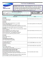
The SMH9207 presents with the symptom of the microwave oven being “DEAD”.
There are no functions available and the oven is incapable of operating at this time. Testing has shown that this problem
can manifest due to a failure of the
ASSY PCB MAIN
which is located in the microwave ovens Door Assy.
To Troubleshoot this failure, you will need a DVM (Digital Voltage Meter) capable of reading both AC and DC
voltages. Use the Images on page three for reference.
Step 1:
Check that AC voltage is available and present in the microwave oven. Check the input voltage at the Noise
Filter PCB Assy. Check for ≈ 120VAC on both the input and output connectors of the PCB.
If the Voltage is not Present, check the input wire harness, outlet for voltage. Also check that the circuit
breaker of fuse supplying the outlet is not open.
If voltage is present at the input of the Noise Filter board, but not present at the output, check the 20 A,
250VAC fuse on the Board. Replace the fuse or board as necessary.
Note: The wiring diagram in the Service Manual for SMH9207 is incorrect. Page 2 cannot be used to locate con-
nectors and pins due to the mislabeling of the connectors. Please use the provided picture on page 3 for cor-
rect connector and pin assignments.
Step 2.:
The configuration of this microwave oven differs with the traditional configurations of ovens by Samsung. The
Logic and Control of the microwave oven has been split between 2 (two) boards where in previous models, all functions
are contained on one board. Unfortunately both of the new boards are described a ASSY PCB MAIN. For the purposes
of troubleshooting, we will refer to the 2 boards as follows:
Relay Circuit Board Assy (ASSY PCB MAIN) - Large board located in ASSY Control BOX
Control Circuit Board Assy (ASSY PCB MAIN) - Located in in the ASSY DOOR
Check if AC voltage is present at the
Relay Circuit Board assy.
(MAIN). Measure for
≈120VAC
between
CN01—Pin 1 (B6)
and the
Neutral line out
of the noise filter Board assy.
(White wire)
. If the voltage is not
present check the following:
1.
MGT TCO
and the
Cavity TCO
for open conditions. Remove power form the microwave oven. Us-
ing an ohmmeter, check for continuity from the noise filter
L voltage output (Black wire)
to
CN01—
pin 1
. If open, check each TCO individually with an ohmmeter and replace as necessary.
If the AC voltage is present at
CN01-Pin1
, check for the presence of the
Main Relay Control Signal (RY-
MAIN)
from the Control Circuit Board which is located in the Door Assy.
1. Using a DC Multi-meter, check for a signal voltage at connector
CN05
on the MAIN PCB. Check
Pin 25
. The signal should read:
≈3.5 vdc
with the door closed.
≈4.5 to 5 vdc
with the door open.
Use the metal ASSY Bracket for DC gnd.
If the signal is not present, this indicates a failure of the Control Circuit Board.(Also called MAIN). A final
check is to look for 5 vdc at CN05—pins 22 and 20. If the 5 vdc is not present, the Control Circuit PCB has
failed. The 5 vdc is created on the relay bd., but is loaded down and won’t be present.
Parts:
Control Circuit Board Assy. Please order:
Relay Circuit Board Assy. This Board is not available as a service part. Please order:
The board is part of this assembly.
DE92-02135A
ASSY PCB MAIN
DE94-02097A
ASSY CONTROL BOX
Содержание SMH9207ST/XAA
Страница 2: ......


