background image

CN03 Gas Sensor      

4-3 5vdc 

CN02 Pwr & Relay                                                      

1-(CN01-1) Vent High                                 
3-(CN01-1)  Vent Mid                             
5-(CN01-1)  Vent Low                               
7-(CN01-1)  TT                                                 
9-(CN01-1)  Main Relay Contact 

Main PCB 

CN01 Relay, Lamp, SMPS                                        

1 Line 1                                                                           
3-1 RY202 In Rush Relay Neutral Contact            
5-1 RY206 Bright Lamp Relay Neutral Contact   
5-1 RY205 Night Lamp Relay Neutral Contact                                                 

RY04

 Power 

Low Relay 

RY03


Power 
High Relay 

RY09             


Vent 
Low 

RY08


TT 

RY01


Main 
Relay 

RY05       

Bright            
Relay 

RY06             

Night                   
Relay 

RY02

 In 

Rush Relay 

Door Interlock Ass’y 

CN04


Door Connector                  

1 Door sw                                    
3 Door sw                                    
3-5 12vdc                                      
4-5 5vdc            

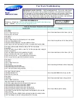
The fuse is located on the noise filter. 

1. 

Disconnect power and remove grille and Assembly 

Control Box. 

2. 

Replace the fuse. 

3. 

When 20A fuse blows out by the operation of interlock 

monitor switch failure, replace the primary interlock 
switch, secondary interlock switch, door sensing switch, 
interlock monitor switch and power relay. 

4. 

When the above four switches operate properly, check 

if any other part such as the control circuit board, blower 
motor or high voltage transformer is defective. 

CN05                               

1) RY-POWER-L 
2) RY-POWER-H 
3) RY-INRUSH 
4) G S 
5) RY-BRIG HT 
6) KEY7-AD 
7) RY-SPARE 
8) VFD FILAM ENT1 
9) RY-NIG HT 
10) VFD FILAM ENT2 
11) RY-VENT-H 
12) RY-O PTIO N 
13) RY-VENT-M           
14) -34V 
15) RY-V_DO O R 
16) G ND 
17) BUZZER 
18) G ND 
19) RY-VENT-L 
20) + 5V 
21) RY-TT 
22) + 5V 
23) INT 
24) TCO -S 
25) RY-M AIN 
26) STB 

CN06                

1-3 5vdc 

RY11


Vent 
High 

RY10


Vent 
Mid 

L1 

L1 

Содержание SMH9207ST/XAA

Страница 1: ...14 for 30 seconds while a weight sensor in operation E 34 The initial value of K calculated by a weight sensor is above and under 28 as value of HEX E 35 The value of A is as a weight sensor calculates E 36 In case the door opens during sensor cooking Error Code Gas Sensor Error Case E 1X E 41 Open E 42 Short E 43 T1 Max Time Error E 44 Dry Up E 45 Cooling Error 3minutes E 46 Primary Open Error 3m...

Страница 2: ......

Страница 3: ...ower and remove grille and Assembly Control Box 2 Replace the fuse 3 When 20A fuse blows out by the operation of interlock monitor switch failure replace the primary interlock switch secondary interlock switch door sensing switch interlock monitor switch and power relay 4 When the above four switches operate properly check if any other part such as the control circuit board blower motor or high vo...

Страница 4: ...nately both of the new boards are described a ASSY PCB MAIN For the purposes of troubleshooting we will refer to the 2 boards as follows Relay Circuit Board Assy ASSY PCB MAIN Large board located in ASSY Control BOX Control Circuit Board Assy ASSY PCB MAIN Located in in the ASSY DOOR Check if AC voltage is present at the Relay Circuit Board assy MAIN Measure for 120VAC between CN01 Pin 1 B6 and th...

Страница 5: ...is present during any cook cycle Before touching any components or wiring always unplug the oven and discharge the high voltage capacitor Some semiconductor solid state devices are easily damaged by static electricity Such components are called Electrostatically Sensitive Devices ESDs Examples include integrated circuits and field effect transistors Immediately before handling any semiconductor co...

Отзывы: