background image

Connecting Peripherals 


      4–5 

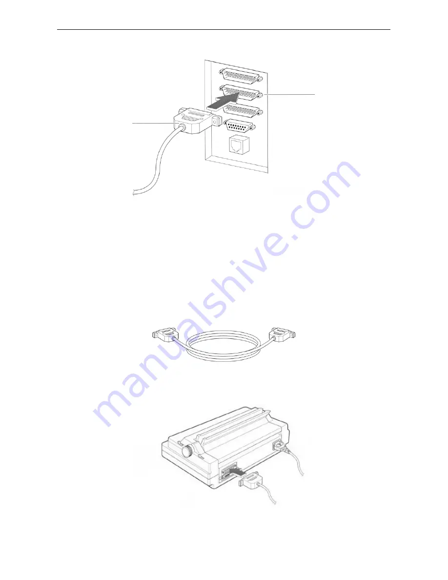
3.  Connect the other end of the cable to one of the serial ports I/O 1 or I/O 2 on the SMG-3000. 


Connecting a Serial Printer 

An SMDR (Station Message Detailed Recording) printer and system printer can be connected to the SMG-
3000 system. The SMDR printer displays information on various calls made in the system. The system 
printer, on the other hand, is used to print status information for the various events that occur in the SMG-
3000 system on a real-time basis. 
 
1. Prepare an RS-232C cable with 25-pin connectors. 


2.  Connect one end of the cable to the 25-pin serial port on the rear of the printer. 


RS-232C cable 

I/O 1 or I/O 2 
port 

Содержание SMG-3000

Страница 1: ...SAMSUNG SMG 3000 INSTALLATION MANUAL MINI DCS GATEWAY ...

Страница 2: ...imer Samsung Telecoms is not responsible for errors or problems arising from customers not installing programming or operating their Samsung systems as described in this manual Copyright 2001 Samsung Telecoms U K Limited All rights reserved No part of this manual may be reproduced in any form or by any means graphic electronic or mechanical including recording taping photocopy or information retri...

Страница 3: ...55022 1998 EN61000 3 2 1995 INC A1 A2 1998 EN61000 3 3 1995 EN55024 1998 AS NZS3548 1995 CTR3 A1 Commission Decision 98 515 EC CTR4 A1 Commission Decision 98 520 EC CTR21 A1 Commission Decision 98 482 EC Manufacturer Samsung Electronics Co Ltd 259 Gongdan Dong Gumi City Kyungbuk Korea 730 030 Sung Chul Hong General Manager place and date of issue name and signature of authorized person Representat...

Страница 4: ...tem may be provided with the ability to communicate with local computer networks to provide CTI functions and features In this case it is capable of passing information to the computer network via a specified link The system is powered by mains voltage and can optionally be powered by batteries Details of all connections and power arrangements are provided in the instructions for use It should not...

Страница 5: ...talling the SMG 3000 System Installation Procedure Checklist 3 1 Basic Requirements 3 1 Safety 3 1 Environmental Conditions 3 1 Grounding the System 3 2 Input Power Supply 3 2 Installing Cables 3 2 Arranging Space for Installation 3 2 Unpacking the System 3 2 Connecting the Power and Battery Cables 3 3 Installing Cards 3 5 Rack Slots 3 5 Procedure 3 5 Connecting Cables to Subscriber Cards 3 8 Prep...

Страница 6: ...cting a Serial Printer 4 5 Chapter 5 System Checking and Operation Before Operation 5 1 Checking Operating Conditions 5 1 Checking Safety Conditions 5 1 Starting the System 5 1 Checking System Functions 5 3 Checking Basic Telephone Functions 5 3 Checking the Attendant Console 5 4 Checking Operation of Peripherals 5 5 Shutting Down the System 5 5 Chapter 6 SMG 3000 System Maintenance and Repair Exc...

Страница 7: ...proved VLSI circuit technology Custom IC design technology System diagnostics program Cost effective Design Features The SMG 3000 system is designed to be cost effective by using optimum card component density at the most competitive price minimising power consumption using CMOS technology components installing components more effectively on the control card expanding system functions more conveni...

Страница 8: ...puter Telephony Integration CTI to provide a number of services by connecting a PC to the system Convenient Maintenance and Repair The system provides the following functions for more convenient maintenance and repair MAP MAP is the SMG 3000 operating software used to maintain and repair the system It runs on the MAP PC and can access change and control all system information Diagnostic Function I...

Страница 9: ...DCS Gateway documentation CD ROM supplied with your system Only details specific to the SMG 3000 system are included in this guide System Structure First let s look at the rack structure of the SMG 3000 system and its components System Rack The system rack comprises a shelf with slots into which power cards a control card and a number of sub scriber cards can be inserted There is a power on off sw...

Страница 10: ...es and searches data controls data transmission to pe ripheral devices and checks and tests the condition of cards This card acts as the interface between different subscriber cards supplies the system clock for SMG 3000 network synchronisation and the system tone source provides the I O interface Subscriber Cards The subscriber cards provide various services to subscribers The SMG 3000 system can...

Страница 11: ...ds and battery read this chapter To install peripherals read Chapter 4 Connecting Peripherals To start and test the basic system functions read Chapter 5 System Checking and Operation Note For information on setting card jumpers and installing the MAP and system software refer to the DCS Gateway documentation CD ROM supplied with your system Basic Requirements The following sections describe the o...

Страница 12: ...esistance should be more than 20kOhm and the earth leak resistance should be in excess of 20kOhm There may be exceptions in special cases It is best to use 24AWG 0 5 mm line for digital subscriber cables Be careful not to locate a subscriber line next to a high voltage line WARNING DANGER OF ELECTRIC SHOCK You are strongly recommended to connect the mains cable supplied to a fused spur rather than...

Страница 13: ...t the rack may tilt if you use an A frame carrier for transport Do not tilt or place the system on its side Always keep it vertical Connecting the Power and Battery Cables Follow the instructions below to connect the power and battery cables to the SMG 3000 system 1 Loosen the screw securing the rear cover and remove the cover 2 Loosen the screw securing the left hand side cover looking from the f...

Страница 14: ...ture below Cut the string wrapped around the power cable 4 Look at the backplane board after you remove the rear cover You will see two connectors for connect ing the power cable and the battery cable Connect the power cable and the battery cable as shown be low Power cable Battery cable Power cable Battery cable ...

Страница 15: ...ristband if you have one Any surface where cards are placed must be wrapped in conducting material and grounded Also place the ground clip connected to the electrostatic proof bag in contact with the surface Try not to touch the edge connectors on the cards or any pins on the jumpers Install the cards as follows The PRI4 card is used as an example in the illustrations however all cards are inserte...

Страница 16: ...d lower ends of the card s front panel 90 degrees to make a right angle with the card as shown 4 Push the card into the slot until it locks Then push the ejectors 90 degrees back to their original posi tions to secure the card firmly to the inner backplane board Guide rail ...

Страница 17: ...Installing the System 3 7 5 Insert two screws into the screw holes at the top and bottom of the card s front panel and tighten ...

Страница 18: ...sts the requirements of each subscriber card Refer to it when you install the MDF Preparing the Cable The cables that connect to the cards look like this The cable has 50 pins numbered serially from 1 to 50 and each pin is designated for a specific card For a detailed description of pin connections refer to the documentation provided on the DCS Gateway CD ROM supplied with your system Connecting t...

Страница 19: ...rom behind the system the connector on the far right is the UCS0 slot and the connector located on the far left is the UCS3 slot Connect the cable to the relevant connector 3 Feed the cable out through the hole located in the lower part of the rear shelf 4 Connect the cable to the MDF 5 Repeat the above procedure for all subscriber cards you have mounted in the rack Backplane board Backplane board...

Страница 20: ... a leased line from the telephone company Installing the Storage Battery Precautions Check that there is no damage to the battery before installation When installing stand the battery on a wooden stand or box so that it does not move or tilt When connecting the battery take care with the polarity Tighten the nut and bolt securely and cover with grease to prevent erosion Fully charge the battery be...

Страница 21: ...erals and terminals can be connected These I O ports are located on the backplane board at the rear of the system and comprise three 25 pin serial ports a 15 pin LAN port and an RJ 45 LAN port The 25 pin serial ports are designated I O 0 I O 1 and I O 2 The 15 pin LAN port is designated I O 3 and the RJ 45 port is designated I O 4 Ports I O 3 and I O 4 are used to connect to the network and cannot...

Страница 22: ...ion Note When you finish installation and start the MAP to configure your system you must enter the parameters for the I O ports on the PMS PC and the SMG 3000 being used Refer to the MAP User Guide on the DCS Gateway CD ROM for details Connecting to a 25 pin Serial Port Using an RS 232C Cable 1 Prepare an RS 232C cable with one 25 pin connector and one 9 pin connector 2 Connect the 9 pin end of t...

Страница 23: ...he I O 4 LAN Port 1 Connect the network LAN UTP cable to the UTP port of the PC 2 Connect the other end of the network cable to the I O 4 port on the SMG 3000 I O 3 port RS 232C cable I O 0 I O 1 or I O 2 port UTP cable I O 4 UTP cable UTP port ...

Страница 24: ...on a PC which is used in hotels and similar establishments The PMS receives details of phone bills the current status of guest rooms etc from the system and monitors activity and prints reports for management purposes 1 Prepare an RS 232C cable with 25 pin connectors that will be used to connect the PMS PC and the SMG 3000 Pin connections are as shown below 2 Connect the PC end of the cable to the...

Страница 25: ...e connected to the SMG 3000 system The SMDR printer displays information on various calls made in the system The system printer on the other hand is used to print status information for the various events that occur in the SMG 3000 system on a real time basis 1 Prepare an RS 232C cable with 25 pin connectors 2 Connect one end of the cable to the 25 pin serial port on the rear of the printer RS 232...

Страница 26: ...to the MAP User Guide on the DCS Gateway CD ROM for details If a problem occurs while operating the SMDR printer follow these steps 1 Confirm that the RS 232C cable between the printer and the SMG 3000 is properly connected 2 Check that the I O connection for the printer is properly designated in the MAP and that the transfer speed is correct 3 In the MAP define a type of call that is to be printe...

Страница 27: ...n equipments Checking Safety Conditions Check that the building is well protected from lightning or leakage of electricity with a lightning rod or ground connection Check that the SMG 3000 system is perfectly upright not tilted and level with the ground Be sure not to put equipment that may cause electromagnetic interference close to the system Be sure to provide a fire extinguisher nearby A sprin...

Страница 28: ...e front panel of the RCMP D card light green and the RING LED on the RGPS K card lights green If any of the LEDs light red immediately switch OFF the power switches on the RCMP D and RGPS K cards and check all cable connections 7 If the RCMP D card and the RGPS K card operate normally switch ON the power switch on the MCPU2 card ...

Страница 29: ...ke sure that it has been assigned a class of service that allows the functions being tested Refer to the user guide supplied with your phone for any function codes required Checking Internal Calls Function Check that communication between internal users is available 1 Lift the handset of an internal telephone and confirm that you can hear internal dial tone 2 Dial the first digit of another intern...

Страница 30: ...e external subscriber without dialling the exter nal dialling code 1 Lift the handset of an internal telephone and dial the external dial code Check that you can hear external dial tone 2 Check that you can hear the busy tone that is generated when all external lines are busy 3 Press the hookflash key on your phone and confirm that the busy signal stops 4 Dial the code for callback and confirm tha...

Страница 31: ...ted to the SMG 3000 system see Chapter 4 Connecting Peripherals Various alarms and event information can be printed and the in formation can be important if problems occur or for monitoring the system s activities Therefore be sure to check the condition of the printer regularly To check the printer 1 Perform a printer self test as described in the user s manual for the printer 2 Check that the RS...

Страница 32: ...cking Operation 2 Turn off the switches on the RCMP D card and RGPS K card 3 Turn off the main power switch located on the left hand side of the system rack to cut off the electricity supplied to the shelf MCPU2 card ...

Страница 33: ...lation Manualincludes procedures for exchanging cards in the system rack see Exchanging Boards in Chapter 7 If you want to exchange subscriber cards using the BDR cable follow the instructions given in the manual but take note of the following Exchanging Subscriber Cards The BDR connector for attaching the BDR cable when exchanging subscriber cards is located on the back plane board of the SMG 300...

Страница 34: ...Samsung Telecoms U K Limited Brookside Business Park Greengate Middleton Manchester M24 1GS Tel 0161 655 1100 Fax 0161 655 1166 ...

Отзывы: