background image

12

 · English


lEd status

LED indicator shows operational status with colors.
Refer to table below for detailed meaning of the LED indicator.

Color

Status

Red

Booting up

Red Blinking

Booting completed / Establishing network connection

Yellow

Enabling Wi-Fi Direct

Blue Blinking

Connecting to the network.

Blue

Local connection established

Green

Connection to server completed / Normal operation

Purple

Updating firmware

network connection  

In a location with a strong Wi-Fi signal and no interference, use Wi-Fi 

communication.

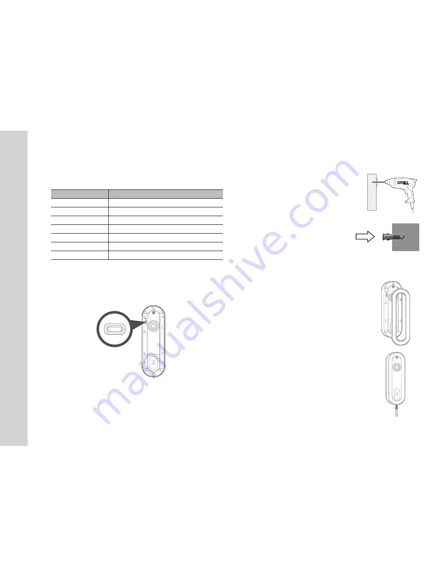
assembling

1. 

Use a drill on the marked positions, and drill holes 

to a depth of 3 cm. Clean the holes after drilling.


J


`

It is recommended to use a drill bit (Ø5) that is suitable 

for the wall material.


`

Be careful not to get injured while drilling.

2. 

Insert an anchor for the two holes. Fully insert 

the anchors by gently tapping the anchor 

head with a hammer or rubber mallet.

3. 

Match the camera to the holes on the door 

and fasten the screw.

4. 

Insert the Deco case into the camera front.

5. 

Tighten the screws to combine the casing.

RESET

RESET

Содержание SMARTCAM D1

Страница 1: ...SNH V6435DN SMARTCAM D1 User Manual ...

Страница 2: ...ion Any changes or modifications not expressly approved by the party responsible for compliance could void the user s authority to operate this equipment This transmitter must not be co located or operating in conjunction with any other antenna or transmitter Industry Canada Statement This device complies with RSS 247 of the Industry Canada Rules Operation is subject to the following two condition...

Страница 3: ...es ex audio amplifier TV etc Make sure to keep ventilated while using the product Avoid pillar or furniture that may block ventilation when installing the product Make sure to use the power adaptor provided If used with unidentified adaptor it may damage the product The power adaptor must be used with regular household electric supply Avoid sharp pointed objects around the adaptor s cable not to d...

Страница 4: ...tents Getting Started Features 5 What s Included 6 Part names and functions 7 Installation Network Connection Installation 9 Network Connection and Settings 13 Appendix Specifications 15 Troubleshooting 19 ...

Страница 5: ...uter Remote monitoring You can monitor your SmartCam D1 remotely at any time and from any location using your smartphone Real time alarm When the bell rings a push alarm is sent to the smartphone Face recognition You can set the person who wants to receive the alarm Downloading a recorded video You can download motion detection audio detection manually recorded video to the user s smartphone Andro...

Страница 6: ...omponents when opening the product package SmartCam D1 Quick Start Guide Option by region Warranty Card GPL Lisence Face cover Secure screw Plastic anchor Drill bit Screw driver Power stabilizer Power stabilizer Cable Power cable Connector ...

Страница 7: ...ting Started Part names and functions Front Rear Deco Case This is a case mounted on the exterior of the SmartCam D1 Bell Button Microphone hole Status LED Power Input This is the AC adapter connection terminal ...

Страница 8: ...less communication between product and smartphone Reset button Resets the product settings to the factory default The system restarts if you press the button for 10 seconds using a pointed object such as a needle J If you press too strongly the button can break Speaker hole ...

Страница 9: ...obstacles 4 When wiping the surface of the product a clean and soft dry cloth should be used Moist the dry cloth with water and wring it thoroughly to remove extra water Do not use cleaners containing alcohol or solvents detergents containing surface active ingredients and skin care products or oil as they can cause damage or deformation of the product 5 Do not install the product in places where ...

Страница 10: ...reaker to cut off the electricity 2 Find existing chime bell in the house following your sound 3 Open the chime cover and unscrew the FRONT TRANS wires with a screwdriver 4 Connect the supplied power cord to the power stabilizer socket 5 Open the holding pins of the enclosed two connectors connect the wire pulled out from FRONT and close the holding pin 6 Connect each L connectors to each of the t...

Страница 11: ...olts AC power installed on the existing chime Check and install a mechanical electronic chime type Install and install the circuit breaker for safety reasons Refer to the Home page for a list of compatible chimes J J Connect the chime type to chime default when connecting the SmartCam D1 to the 16 AC adapter Transformer Connection Structure Existing installation structures have been removed from t...

Страница 12: ...tion In a location with a strong Wi Fi signal and no interference use Wi Fi communication Assembling 1 Use a drill on the marked positions and drill holes to a depth of 3 cm Clean the holes after drilling J J It is recommended to use a drill bit Ø5 that is suitable for the wall material Be careful not to get injured while drilling 2 Insert an anchor for the two holes Fully insert the anchors by ge...

Страница 13: ...ic load According to the network policy of the Internet service provider UDP blocking video reception may be limited to 7 minutes In addition to the above two situations you may encounter a network delay or interruption due to the network conditions Some hubs can have compatibility issues Network Connection and Settings Connection using the Wi Fi Direct function What is Wi Fi Direct If you use Wi ...

Страница 14: ...obile device 1 Go to Google Play App Store and search for Wisenet SmartCam 2 Download the application and install it on your mobile device 3 Run the downloaded application 4 After completing member registration register the SmartCam D1 as instructed on the screen n n For more details refer to Wisenet SmartCam mobile guide iOS Android ...

Страница 15: ...565 V Effective Pixels 2065 H x 1553 V Scanning System Progressive Min Illumination B W 0 Lux with IR Lens Focal Length 2 29mm Max Aperture Ratio F 2 2 Angular Field of View H V D D 154 3 H 125 V 94 8 Min Object Distance 0 2m Focus Control Fixed Focus Mount Type Wall mount bracket with secure screw Lens Distortion Correction Support Camera level Specifications Specifications ...

Страница 16: ...m Description Alarm Triggers Combination of events Body Detection Motion Zone Selection Customizable Event action Alarm Events Push Alert Mobile Device Notification via e mail Memory Slot N A Cloud Storage Support for North America only Booting Time Max 30sec Factory reset Support Pin hole button Network Ethernet N A Wireless WiFi 802 11a b g n ac Dual Band Video Delay Latency Max 1000ms Internet ...

Страница 17: ...at Unicast Mode Webpage Language N A Web App viewer Web viewer not supported Supported OS iOS Android Central Management Software N A Environmental Operating Temperature Humidity 20 C 40 C Less than 90 RH Storage Temperature Humidity 30 C 50 C Less than 90 RH Ingress Protection Weather Resistant Item Description Electrical Input Voltage Current Wired AC 16 24VAC 10VA Power Consumption Max 7W Power...

Страница 18: ...18 English Product Appearance unit mm inch unit mm inch ...

Страница 19: ...econds The product will be restarted when the product is factory reset Problem Action The video from the camera is temporarily lost The video from the camera can be delayed according to a network delay Check if the product and the camera are far apart No sound is output from the video Click the Voice icon in the video playback page or check if the voice is turned On in your smart phone app Some in...

Страница 20: ...e sustainable reuse of material resources Household users should contact either the retailer where they purchased this product or their local government office for details of where and how they can take these items for environmentally safe recycling Business users should contact their supplier and check the terms and conditions of the purchase contract This product and its electronic accessories s...

Страница 21: ...47 8753 Fax 82 31 8018 3740 www wisenetlife com Hanwha Techwin America 500 Frank W Burr Blvd Suite 43 Teaneck NJ 07666 Tel 1 877 349 3149 www wisenetlife com Hanwha Techwin Europe Heriot House Heriot Road Chertsey Surrey KT16 9DT United Kingdom Tel 1 00800 801 08022 Tel 2 31 77 326 1580 www wisenetlife com ...

Страница 22: ...may cause harmful interference to radio communications However there is no guarantee that interference will not occur in a particular installation If this equipment does cause harmful interference to radio or television reception which can be determined by turning the equipment off and on the user is encouraged to correct the interference by one of the following measures Reorient or relocate the r...

Страница 23: ...nly This device meets all other requirements specified in Part 15E Section 15 407 of the FCC Rules Industry Canada Statement This device complies with RSS 247 of the Industry Canada Rules Operation is subject to the following two conditions 1 This device may not cause harmful interference and 2 this device must accept any interference received including interference that may cause undesired operat...

Страница 24: ...us les utilisateurs devraient aussi être avisés que les utilisateurs de radars de haute puissance sont désignés utilisateurs principaux c à d qu ils ont la priorité pour les bandes 5 250 5 350 MHz et 5 650 5 850 MHz et que ces radars pourraient causer du brouillage et ou des dommages aux dispositifs LAN EL Industry Canada Radiation Exposure Statement This equipment complies with IC radiation expos...

Отзывы: