2. Product specification and description
2.2.6. Engine F/W Control Algorithm
2.2.6.1. Feeding
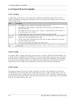
If feeding from a cassette, the drive of the pickup roller is controlled by controlling the solenoid. The on/off of the
solenoid is controlled by controlling the general output port or the external output port. While paper moves, occurrence
of Jam is judged as below.
Item
Description
Jam in Tray 1
•
After picking up, paper cannot be entered because to paper is not fed.
•
After picking up, paper entered but it cannot reach to the feed sensor in predetermined period of
time. due to slip, etc.
•
After picking up, if the feed sensor is not on, re-pick up. After re-picking up, if the feed sensor is
not on after certain time, it is JAM 0.
•
Even though the paper reaches to the feed sensor, the feed sensor doesn’t be ON.
Jam inside
machine
•
After the leading edge of the paper passes the feed sensor, the trailing edge of the paper cannot pass
the feed sensor after predetermined period of time.
•
After the leading edge of the paper passes the feed sensor, the paper cannot reach the exit sensor
after predetermined period of time.
* The paper exists between the feed sensor and the exit sensor.
Jam in Exit
area
After the trailing edge of the paper passes the feed sensor, the paper cannot pass the exit sensor predetermined
period of time.
2.2.6.2. Transfer
The charging voltage, developing voltage and the transfer voltage are controlled by PWM (Pulse Width Modulation). The
each output voltage is changeable due to the PWM duty. The transfer voltage admitted when the paper passes the transfer
roller is decided by environment conditions. The resistance value of the transfer roller is changed due to the surrounding
environment or the environment of the set, and the voltage value, which changes due to the environments, is changed
through AD converter. The voltage value for impressing to the transfer roller is decided by the changed value.
2.2.6.3. Fusing
The temperature change of the heat roller’s surface is changed to the resistance value through the use of a thermistor.
The Main Board uses the resistance value of the Thermistor and converts it to a voltage value through the use of an AD
converter, the temperature is decided based on the voltage value read. The AC power is controlled by comparing the target
temperature to the value from the thermistor. If the value from the thermistor is out of controlling range while controlling the
fusing, the error stated in the below table occurs.
2-34
Copyright© 1995-2013 SAMSUNG. All rights reserved.

