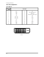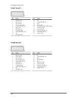
3 Alignments and Adjustments
3-12
3-4-3 Conditions for Measurement
1. On the basis of toshiba ABL pattern : High Light level (57 IRE)
- INPUT SIGNAL GENERATOR : MSPG-925LTH
* Mode NO 2 : 744X484@60 Hz
NO 6 : 1280X720@60 Hz
NO 21 : 1024X768@60 Hz
* Pattern NO 36 : 16 Color Pattern
NO 16 : Toshiba ABL Pattern
2. Optical measuring device : CA210 (FL)
Please use the MSPG-925 LTH generator for model LE26M51B/LE32M51B/LE40M51B/LE46M51B.
3-4-4 Method of Adjustment
1. Adjust the white balance of AV, Component and DVI Modes.
(AV
Component)
a) Set the input to the mode in which the adjustment will be made
(RF
DTV PC DVI).
* Input signal - VIDEO Mode : Model #2 (744*484 Mode), Pattern #16
- DTV,DVI Mode : Model #6 (1280*720 Mode), Pattern #16
- HDMI Mode: Model #6(1280*720 Mode), Pattern #16
b) Enter factory color control, confirm the data.
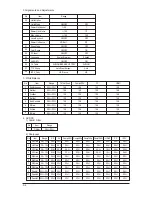
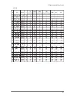
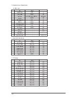
c) Adjust the low light. (Refer to table 1, 2 in adjustment position by mode)
- Adjust sub - Brightness to set the 'Y' value.
- Adjust red offset ('x') and blue offset ('y') to the color coordinates.
* Do not adjust green offset data.
d) Adjust the high light. (Refer to table 1, 2 in adjustment position by mode)
- Adjust red gain ('x') and blue gain ('y') to the color coordinates.
* Do not adjust the green gain and sub-contrast (Y) data.
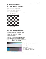
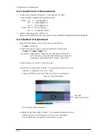
Picture 4-2 Flat W/B Pattern
Low light
Measurement point
Содержание LE23R87BD
Страница 35: ...11 Disassembly and Reassembly 11 4 Description Picture Description 6 Remove screws and lift up the BRKT ...
Страница 37: ...11 Disassembly and Reassembly 11 6 Memo ...
Страница 40: ...13 Circuit Descriptions 13 3 13 2 Main Block ...
Страница 47: ...13 Circuit Descriptions 13 10 13 3 9 HOT Balance Block Diagram 13 3 10 COLD Balance Block Diagram ...
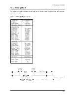
Страница 79: ...14 Reference Infomation 14 8 14 3 2 Supported Modes 1 ...
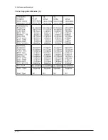
Страница 80: ...14 Reference Infomation 14 9 14 3 3 Supported Modes 2 ...
Страница 81: ...14 Reference Infomation 14 10 14 3 4 Supported Modes 3 ...
Страница 87: ...Memo 14 Reference Infomation 14 16 ...
Страница 88: ...7 Block Diagrams 7 1 7 Block Diagram This Document can not be used without Samsung s authorization ...
Страница 89: ...7 Block Diagrams 7 2 Memo ...
Страница 101: ...2 Product Specifications 2 12 Memo ...
Страница 104: ...5 Exploded View Parts List 5 3 5 3 LE26R86BD Exploded View T0003 T0175 M0215 T0447 M0115 M0014 M0107 M0013 M0013 ...
Страница 106: ...5 Exploded View Parts List 5 5 5 5 LE32R86BD Exploded View T0003 M0215 T0447 M0115 M0013 M0013 ...
Страница 108: ...5 Exploded View Parts List 5 7 5 7 LE37R87BD Exploded View T0003 M0215 M0013 M0013 T0447 M0115 M0146 M0146 M0107 M0014 ...
Страница 110: ...5 Exploded View Parts List 5 9 5 9 LE40R87BD Exploded View T0003 M0215 M0013 M0013 T0447 M0146 M0146 M0107 M0014 ...
Страница 112: ...12 PCB Diagram 12 1 12 PCB Diagram 12 1 Main PCB Diagram FOR READY ...
Страница 113: ...12 PCB Diagram 12 2 12 2 Main PCB Diagram FOR IDTV ...
Страница 114: ...12 PCB Diagram 12 3 12 3 23 SMPS ...
Страница 115: ...12 PCB Diagram 12 4 12 4 26 32 SMPS ...
Страница 116: ...12 PCB Diagram 12 5 12 5 37 SMPS ...
Страница 117: ...12 PCB Diagram 12 6 12 6 40 IP Board ...

