


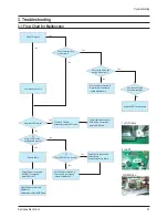

Alignment and Adjustments
Samsung Electronics
2-19
No
Description
Key Point
Remark
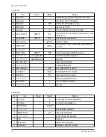
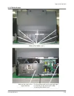
1
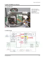
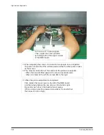
1) When the power cord is plugged in,
2) DC 380V is automatically supplied to the ballast.
Check whether the DC380V
power is supplied to the ballast.
2
1) When the power key is pressed via the remote control, the micom
of the digital board outputs high (5V) PWR signals.
2) The power board operates normally.
5V and 12V are supplied to the DMD CN105 terminal.
Check whether 5V and 12V are
supplied to the CN105 terminal.
* 12V must be supplied to operate the motor.
(The voltage of the motor driving power is 12V.)
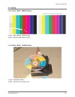
3
1) The MTR Reset signal is supplied to the R161 terminal of the
motor IC101 from the micom on the digital board and then the
motor starts to drive.
2) If the color wheel rotates for a certain time and then stops, check
whether the color wheel sensor is normal.
(Check the waveform on the No.2 terminal below CN102.)
After the set is powered on, check
whether 5V is detected on pin
No.49 of IC101.
→
After a while, the sound
generated by the rotating color
wheel is heard.
* If 5V is not detected, the motor will not operate.
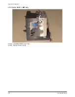
4
1) Check whether the signal (SCI: START CONTROL INPUT)
that turns on lamp #2 of CN109 on the DMD board is high (5V).
Check whether CN109 #2 signal
is 5V.
* When SCI is high (5V), the lamp litz of CN109
is low (0V).
* CN109 #2 terminal voltage changes to pulse
wave form 14 seconds after (for 50 inch TV)
the time that the voltage is 5V.
* When about 4 seconds have passed after
changing to pulse waveform, the screens are
displayed on the set.
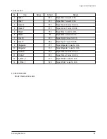
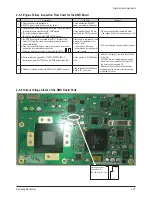
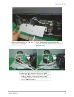
5 1) Method for checking whether the DDP1010 IC RESET is normal.
If the voltage between R254 and
R255 is 3V, it is normal.
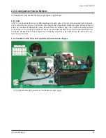
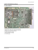
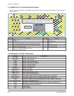
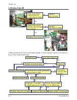
2-9-5 Engine Failure Inspection Flow Chart for the DMD Board
2-9-6 Output Voltage States of the DMD Board Parts
Output terminal
Wave form for
RA101,102,103,104
Содержание HL-R5677W - 56" Rear Projection TV
Страница 4: ...1 2 Samsung Electronics MEMO ...
Страница 34: ...2 30 Samsung Electronics MEMO ...