11
Ins
tallation Pr
oc
edur
e
English
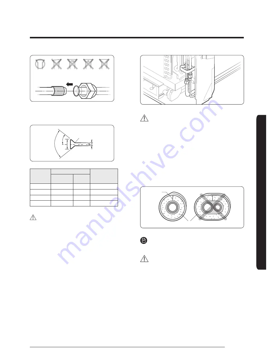
Inclined
Damaged
Surface
Cracked
Uneven
Thickness
6
Align the pipes and tighten the flare nuts first
manually and then with a torque wrench, applying
the following torque.
R 0.4~0.8
90°±2°
45
°±2°
L
D
Outer
diameter (D,
mm)
Connection Torque
Flare dimension
(L, mm)
kgf•cm
N•m
6.35
140~180
14~18
8.70~9.10
9.52
350~430
34~42
12.80~13.20
2.70
500~620
49~61
16.20~16.60
15.88
690~830
68~82
19.30~19.70
CAUTION
In case of needing brazing, you must work with nitrogen
gas blowing.
Step 7 Performing the gas leak test
To identify potential gas leaks on the indoor unit, inspect
the connection area of each refrigerant pipe using a leak
detector for R-410A.
Before recreating the vacuum and recirculating the
refrigerant gas, pressurize the whole system with
nitrogen (using a cylinder with a pressure reducer) at a
pressure above 4 MPa in order to immediately detect
leaks on the refrigerant fittings.
Made vacuum for 15 minutes and pressurizing system
with nitrogen.
CAUTION
• If the pipes require brazing ensure that OFN (Oxygen
Free Nitrogen) is flowing through the system.
Step 8 Insulating the refrigerant
pipes
Once you have checked that there are no leaks in the
system, you can insulate the piping and hose.
1
To avoid condensation problems, place Acrylonitrile
Butadien Rubber separately around each refrigerant pipe.
No gap
NBR
NOTE
• Always make the seam of pipes face upwards.
CAUTION
• The insulation has to be produced in full compliance
of European regulation reg. EEC / EU 2037/ 2000
that requires the use of sheaths insulation form
without using CFC and HCFC gases for health and the
environment.
2
Wind insulating tape around the pipes and drain hose
avoiding compressing the insulation too much.
Содержание AE022MNJDEH
Страница 34: ......


