


EB 8384-1 EN
41
Connections
5
Connections
WARNING!
Risk of injury due to the actuator
stem extending or retracting.
Do not touch or block the actuator
stem.
NOTICE
Risk of malfunction due to incorrect
sequence of mounting, installation
and start-up.
Keep the following sequence.
1. Remove the protective film from the
pneumatic connections.
2.
Mount the positioner on the control
valve.
3.
Connect the supply air.
4.
Connect the electrical power.
5. Perform the start-up settings.
5.1
Pneumatic connections
NOTICE
Malfunction due to incorrect connection
of the supply air.
Do not connect the compressed air
directly to the threaded connections
in the positioner housing. Screw the
screw fittings into the connecting
plate, pressure gauge mounting
block or connection block from the
accessories.
The pneumatic connections in the connecting
plate, pressure gauge mounting block and
connection block are optionally designed as
a bore with ¼ NPT or G ¼ thread. Custom-
ary fittings for metal or copper tubing or
plastic hoses can be used.
NOTICE
Risk of malfunction due to failure to
comply with required air quality.
Only use supply air that is dry and
free of oil and dust.
Read the maintenance instructions for
upstream pressure reducing stations.
Blow through all air pipes and hoses
thoroughly before connecting them.
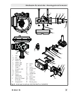
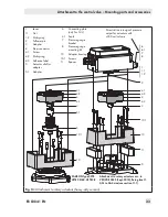
If the positioner is attached directly to the
Type 3277 Actuator, the connection of the
positioner's output pressure to the actuator is
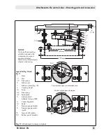
fixed. For attachment according to
IEC 60534-6 (NAMUR), the signal pressure
can be routed to either the top or bottom di-
aphragm chamber of the actuator, depend-
ing on the actuator's fail-safe action "actua-
tor stem extends" or "actuator stem retracts".
For rotary actuators, the manufacturer's
specifications for connection apply.
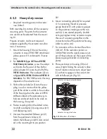
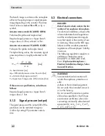
5.1.1
Signal pressure gauges
To monitor the supply air (supply) and signal
pressure (output), we recommend mounting
pressure gauges (see accessories in Table 1
to Table 6).
5.1.2
Supply pressure
The required supply air pressure depends on
the bench range and the actuator's operat-
ing direction (fail-safe action).
Содержание TROVIS 3730-1
Страница 64: ...64 EB 8384 1 EN...
Страница 65: ...EB 8384 1 EN 65...
Страница 66: ...66 EB 8384 1 EN...
Страница 67: ...EB 8384 1 EN 67...
Страница 68: ...68 EB 8384 1 EN...
Страница 69: ...EB 8384 1 EN 69...
Страница 70: ...70 EB 8384 1 EN...
Страница 71: ...EB 8384 1 EN 71...
Страница 72: ...72 EB 8384 1 EN...
Страница 73: ...EB 8384 1 EN 73...
Страница 74: ...74 EB 8384 1 EN...
Страница 75: ...EB 8384 1 EN 75...


