manualshive.com logo in svg
background image

7

Operating the S 2-way

SETTING UP THE S 2-way FOR STEREO 2-way OPERATION

The following operating example is for a Stereo 2-way system using a 15" low frequency driver and a 1" compres-
sion driver on both the left and right sides.  

CAUTION:

Before you apply power to your speaker system amplifiers, be certain to set the frequency controls to

the manufacturers recommended crossover points for the drivers or enclosures you are using. 

NOTE: LAST ON / FIRST OFF

When running a loudspeaker system with one or multiple power amplifiers, it is highly recommended that you fol-
low the LAST ON / FIRST OFF rule.  When powering up your sound system, turn your power amplifier on last.
When you power down your system,  turn your power amplifiers off first.  This will prevent any switching spikes
you may get from other gear in your system, and help prevent unnecessary pops that can sometimes cause
speaker damage. 

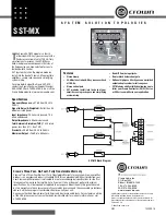
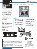
Connect both sets of inputs and outputs to the designated connectors on the rear panel. For a detailed
cable-wiring diagram see page 13.

*

Set the controls to the following positions:

INPUT GAIN 

-12 

DELAY

0

LOW GAIN

-6

LOW/MID FREQUENCY

2.6 kHz

RANGE SWITCH

IN

HIGH GAIN

-6

MODE SWITCH

ST 2W

HIGH PHASE

OUT

LOW PHASE

OUT

HIGH MUTE

IN

LOW MUTE

IN

Set the controls for the S 2-way’s Channel 2 to the same positions.

Set the Power Switch to the ON position.

Connect the mixer’s left output to the S 2-way’s CH1 (Left) input and the mixer’s right output to the S 2-
way’s CH2 (Right) input.  Next, connect the S 2-way’s CH1 (Left) Low Output to the left input of the
power amp operating the low frequency drivers, and then, connect the CH1 High Output to the left input
of the power amp operating the High frequency drivers.  Now, make the same connections for the S 2-
way’s CH2(Right) and amplifiers right side.

Содержание S Class

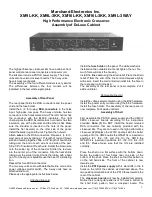
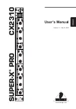
Страница 1: ...S C l a s s S i g n a l P r o c e s s o r s STEREO MONO CROSSOVER...

Страница 2: ...objects have fallen into the unit the unit has been exposed to rain or moisture does not operate normally or has been dropped PRECAUCION Para reducir el riesgo de incendios o descargas no permita que...

Страница 3: ...on 7 8 S 2 way Controls 9 S 2 Way System Set Ups Mono 3 way Operation 10 SETTING UP THE S 2 way USING A REAL TIME ANALYZER 11 12 S 2 way Connections 13 Block Diagram 14 Specifications 15 Notes 16 Copy...

Страница 4: ...electronic crossover solution which will give you precise control and superior sound from your loudspeaker system In these pages you ll find a detailed description of the features of the S 2 way elect...

Страница 5: ...ows to adjust frequency range of the filter allowing you to change from mid band to high band The four segment LED Input Gain meter allows you to monitor the signal level and make easy gain adjustment...

Страница 6: ...hannel 2 low frequency output This control has no effect when oper ating in stereo 3 way mode 15 LOW GAIN CONTROL CH 2 Adjusts the output level of the LOW frequency band for right in stereo 2 way mode...

Страница 7: ...utput G CHANNEL 1 INPUT MONO INPUT XLR bal anced line input A AC INLET IEC standard ac power cable connec tor with external fuse B CHANNEL 2 HIGH OUTPUT MONO HIGH OUT PUT XLR balanced line output C CH...

Страница 8: ...band that the control The 3 way parameters for these switches and control knobs are indicated by the outlined box MONO 3 WAY INDICATORS Because the S 2 way can be configured to operate in either ster...

Страница 9: ...m other gear in your system and help prevent unnecessary pops that can sometimes cause speaker damage Connect both sets of inputs and outputs to the designated connectors on the rear panel For a detai...

Страница 10: ...raise the output faders until you see the Input Meter LED s begin to light Slowly raise the S 2 way s Input Gains until the Input Meters read 0dB Now raise your power amps to their normal operating le...

Страница 11: ...ing speaker stacks S 2 way Controls HIGH PASS FILTER The S 2 way incorporates a HPF High Pass Filter which when engaged activates a low frequency roll off at 25 Hz By using the HPF you elimi nate the...

Страница 12: ...g the mid and high by using Channel 2 s crossover FREQ control Now adjust the first gain control on Channel 1 to set the level of the LOW frequency output Next adjust the second gain control on Channe...

Страница 13: ...nd compression drivers mounted on a large horn With no correction the low frequency signal can be traveling through the air 2 to 24 in front of the high frequencies and thereby reaching the listeners...

Страница 14: ...wave tuned to the crossover frequency or connect the signal from a pink noise generator to your loudspeaker system either from your mixer or directly in the S 2 way s input Now turn off the Low Frequ...

Страница 15: ...13 Connections Unbalanced 1 4 Connector Balanced TRS 1 4 Connector XLR Balanced Wiring Guide...

Страница 16: ...14 Block Diagram...

Страница 17: ...Type Linkwitz Riley 24 dB Octave Crossover 1 Channel 1 35 to 800Hz 350 to 8kHz with 10X multiplier Crossover 1 Channel 2 35 to 800Hz 350 to 8kHz with 10X multiplier Function Switches Front Panel High...

Страница 18: ...Notes 16...

Страница 19: ......

Страница 20: ...Samson Technologies Corp 575 Underhill Blvd P O Box 9031 Syosset NY 11791 9031 Phone 1 800 3 SAMSON 1 800 372 6766 Fax 516 364 3888 www samsontech com...

Отзывы: