


SETTING UP THE S 2-way USING A REAL TIME ANALYZER
11
SETTING UP THE S•2-way USING A REAL TIME ANALYZER
A REAL TIME ANALYZER (RTA) is an especially useful tool for setting up your crossover, as it will enable you
to set parameters like DELAY and LEVEL more accurately. Some Audio Engineers can use their ears to tune a
loudspeaker system. Some will even use the crossover to create the over-all system curve by using the
crossover like an equalizer. For the rest of us, an accurately set crossover with a flat response is the best way
to start and using a RTA, like the Samson D1500, is the best way to get there.
Using the RTA to Set DELAY Time
.
In the real world, no single or multiple speaker system is perfect. If there were such a perfect system, it would
more than likely be comprised of a single transducer that alone could faithfully reproduce the entire frequency
spectrum. Because no such system exists, we have to deal with the problems associated with multiple trans-
ducers. The first problem that you will encounter, whether you know it or not, is time travel. That’s when the S
2-way’s delay circuit becomes especially useful.
Ideally, the sound reproduced by each driver in the loudspeaker system would be traveling through the air ulti-
mately reaching the listeners at the same time. To accomplish this in a system using multiple drivers or enclo-
sures, the voice coils of all the drivers would have to be lined up on the same vertical axis. This is very difficult
to achieve in many cases because of the physical size of the different components, and the position of the dri-
vers in their enclosures. It is not uncommon to have a physical distance of 2” to 24" or more between the low
and high frequency drivers. For example, front loaded low frequency drivers and compression drivers mounted
on a large horn. With no correction, the low frequency signal can be traveling through the air 2" to 24" in front of
the high frequencies and thereby reaching the listeners at different times. Although the delay time between the
low and high frequency signal may be relatively small, the negative effects can be substantial. The problem is
that both drivers are reproducing frequencies at and around the crossover point, which arrive at the listeners at
different times. Typically, the resulting problem is comb filtering or cancellations at the crossover frequencies.
Using delay greatly helps to improve phasing problems (especially with low frequency drivers) and will help you
achieve a tighter, punchy low end response.
The S 2-way features a DELAY control allowing you to dial up to 2 milliseconds of delay. By using an RTA
and the S 2-way’s DELAY, you can time align the drivers in your system and minimize the possibilities of comb
filtering. Now follow these steps, separately, for both the left and rights sides of your loudspeaker:
•
Set the crossover to the desired frequencies and press all the Mute switches to the ON position, turning
all of the S 2-ways outputs off. Position your measurement microphone approximately 15 feet from
your loudspeaker array, halfway between the low and high frequency drivers. Now turn all the GAIN
controls to the fully counter clockwise position.
•
Play a sine wave tuned to the crossover frequency, or connect a pink noise generator to your loud-
speaker system either from your mixer or in the S 2-way’s input. Now turn off the Low Frequency Mute
switch and adjust the S 2-way’s INPUT GAIN to "0”. Adjust the LOW GAIN control so that the signal is
playing at a loud, but not too painful level. Make sure you only hear sound from the low frequency dri-
ver.
•
Adjust the level control of the RTA until it reads OdB at the crossover frequency. Now press the LOW
MUTE switch turning off the low frequency output.
Содержание S Class
Страница 1: ...S C l a s s S i g n a l P r o c e s s o r s STEREO MONO CROSSOVER...
Страница 15: ...13 Connections Unbalanced 1 4 Connector Balanced TRS 1 4 Connector XLR Balanced Wiring Guide...
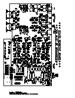
Страница 16: ...14 Block Diagram...
Страница 18: ...Notes 16...
Страница 19: ......