


EB 5206 EN
5-3
Installation
5.4
Thermostat with ther
-
mowell
Measures for preparation before mounting
the thermowell
The sensors of double thermostats share the
same thermowell (see Annex).
Before fastening the thermostat, uncoil the
capillary tube to the required length:
− For wall mounting, the required length
depends on the required capillary tube
and length of the thermowell
− For mounting the thermostat on tanks/in
pipes, the required length depends on
the length of the thermowell
Risk of thermostat malfunction due to
measuring fluid escaping upon breakage of
the capillary tube.
Î
Do not bend the capillary tube.
Î
Do not cut the capillary tube.
Î
Do not pull at the sensor on uncoiling the
capillary tube.
Î
Do not use a smaller bending radius
than 5 mm.
1. Unscrew the front cover of the thermo
-
stat.
2. Detach the sensor from the back of the
thermostat.
3. Route the sensor through the back of the
housing to the front.
Note
NOTICE
!
4. Uncoil the capillary to the required
length (see Fig. 5-5).
5. Route the sensor again through the back
of the housing (see Fig. 5-5).
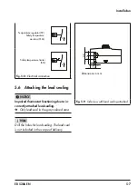
6. Insert seal (6) as shown in Fig. 5-6 or
Î
Proceed as described in section 5.4.1 or
in section 5.4.2 depending on how the
thermostat is to be mounted.
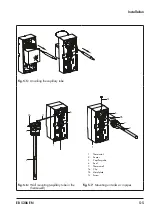
5.4.1 Wall mounting
The thermostat is fastened to the wall using
two screws (not included in the scope of de
-
livery).
1. Drill holes in wall as shown in Fig. 5-4.
2. Insert the seal (6).
3. Fix the capillary tube in the notch at the
side of the thermostat housing or let it
run down the middle (see Fig. 5-6).
4. Fasten the back of the housing (1) using
two screws to the wall.
5. Screw the thermowell (7) into the pipe or
tank.
6. Push the sensor (2) as far as it will go in
-
to the thermowell (7).
7. Fasten the capillary tube (3) to the ther
-
mowell (7) using the supplied clip (7a).
8. Connect the wiring as shown in sec
-
9. Screw the front cover back onto the ther
-
mostat.
Temperature regulators (TR):
Î
Place the set point adjuster on the shaft.
Содержание 5343
Страница 12: ...2 2 EB 5206 EN...
Страница 22: ...3 10 EB 5206 EN...
Страница 32: ...5 8 EB 5206 EN...
Страница 34: ...6 2 EB 5206 EN...
Страница 36: ...7 2 EB 5206 EN...
Страница 38: ...8 2 EB 5206 EN...
Страница 42: ...10 2 EB 5206 EN...
Страница 44: ...11 2 EB 5206 EN...
Страница 48: ...13 2 EB 5206 EN...
Страница 50: ...14 2 EB 5206 EN...
Страница 55: ...EB 5206 EN 15 5 Certificates TR CU certificate...
Страница 56: ...15 6 EB 5206 EN Certificates...
Страница 59: ......


