EB 8355-2 EN
5-19
Installation
Actuator stem extends (FA): fail-close
(for globe and angle valves)
Required supply pressure =
Upper bench range value + 0.2 bar,
at least 1.4 bar.
Actuator stem retracts (FE): fail-open
(for globe and angle valves)
For tight-closing valves, the maximum signal
pressure pstmax is roughly estimated as fol-
lows:
pst
max
= F +
d² · π · ∆p
[bar]
4 · A
d
= Seat diameter [cm]
∆p
= Differential pressure across the valve
[bar]
A =
Actuator area [cm²]
F
= Upper bench range value of the
actuator [bar]
If there are no specifications, calculate as
follows:
Required supply pressure =
Upper bench range value + 1 bar
Pressure regulator
After tilting the cover plate back, the pres-
sure regulator (9) can be continuously ad-
justed. When the adjuster is turned counter-
clockwise as far as it will go, signal pres-
sures for spring ranges up to 2.5 bar are
controlled. When the adjuster is turned
clockwise all the way, signal pressures for
spring ranges up to 6.0 bar are controlled.
If the signal pressure must not exceed a cer-
tain value, this limit can be adjusted using a
pressure gauge (accessories).
5.5
Adjusting the positioner
Intrinsic safety rendered ineffective in in-
trinsically safe devices.
Î
Only connect intrinsically safe devices in-
tended for use in intrinsically safe circuits
to certified intrinsically safe input-con
-
nected units.
Î
Do not place intrinsically safe devices
back into operation that were connected
to intrinsically safe input-connected units
without certification.
Î
Do not exceed the maximum permissible
electric values specified in the EC type
examination certificates when intercon
-
necting intrinsically safe electrical equip-
ment (U
i
or U
0
, l
i
or I
0
, P
i
or P
0
, C
i
or C
0
and L
i
or L
0
).
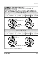
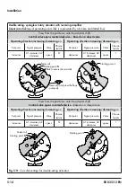
Starting point and set point
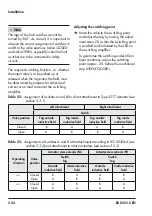
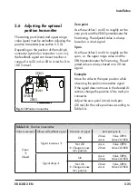
When adjusting the positioner directly at the
control valve, the travel (opening angle) must
be adapted to the set point.
−
With a set point, for example 4 to
20 mA, the valve must move through its
entire travel range from 0 to 100 %
, top).
−
On mounting the positioner on rotary ac-
tuators, an opening angle, for example 0
to 70° must be assigned to the set point.
−
The starting point is based on the
CLOSED position of the valve. Depend-
ing on the control valve version ("actua-
tor stem extends" or "actuator stem re-
tracts") and the operating direction of the
WARNING
!
Содержание 3767
Страница 10: ...1 6 EB 8355 2 EN...
Страница 14: ...2 4 EB 8355 2 EN...
Страница 58: ...6 2 EB 8355 2 EN...
Страница 60: ...7 2 EB 8355 2 EN...
Страница 70: ...10 2 EB 8355 2 EN...
Страница 72: ...11 2 EB 8355 2 EN...
Страница 74: ...12 2 EB 8355 2 EN...
Страница 76: ...13 2 EB 8355 2 EN...
Страница 78: ...14 2 EB 8355 2 EN...
Страница 79: ...EB 8355 2 EN 14 3...
Страница 80: ...14 4 EB 8355 2 EN...
Страница 81: ...EB 8355 2 EN 14 5...
Страница 88: ...14 12 EB 8355 2 EN...
Страница 89: ...EB 8355 2 EN 14 13...
Страница 90: ...14 14 EB 8355 2 EN...
Страница 91: ...EB 8355 2 EN 14 15...
Страница 92: ...14 16 EB 8355 2 EN...
Страница 93: ...EB 8355 2 EN 14 17...
Страница 94: ...14 18 EB 8355 2 EN...
Страница 95: ...EB 8355 2 EN 14 19...
Страница 96: ...14 20 EB 8355 2 EN...
Страница 97: ...EB 8355 2 EN 14 21...
Страница 98: ...14 22 EB 8355 2 EN...
Страница 99: ...EB 8355 2 EN 14 23...
Страница 100: ...14 24 EB 8355 2 EN...
Страница 101: ...EB 8355 2 EN 14 25...
Страница 102: ...14 26 EB 8355 2 EN...
Страница 103: ...EB 8355 2 EN 14 27...
Страница 104: ...14 28 EB 8355 2 EN...
Страница 109: ......
Страница 110: ...2 EB 8355 2 EN...
Страница 111: ...EB 8355 2 EN 3...


