


EB 8385 EN
7
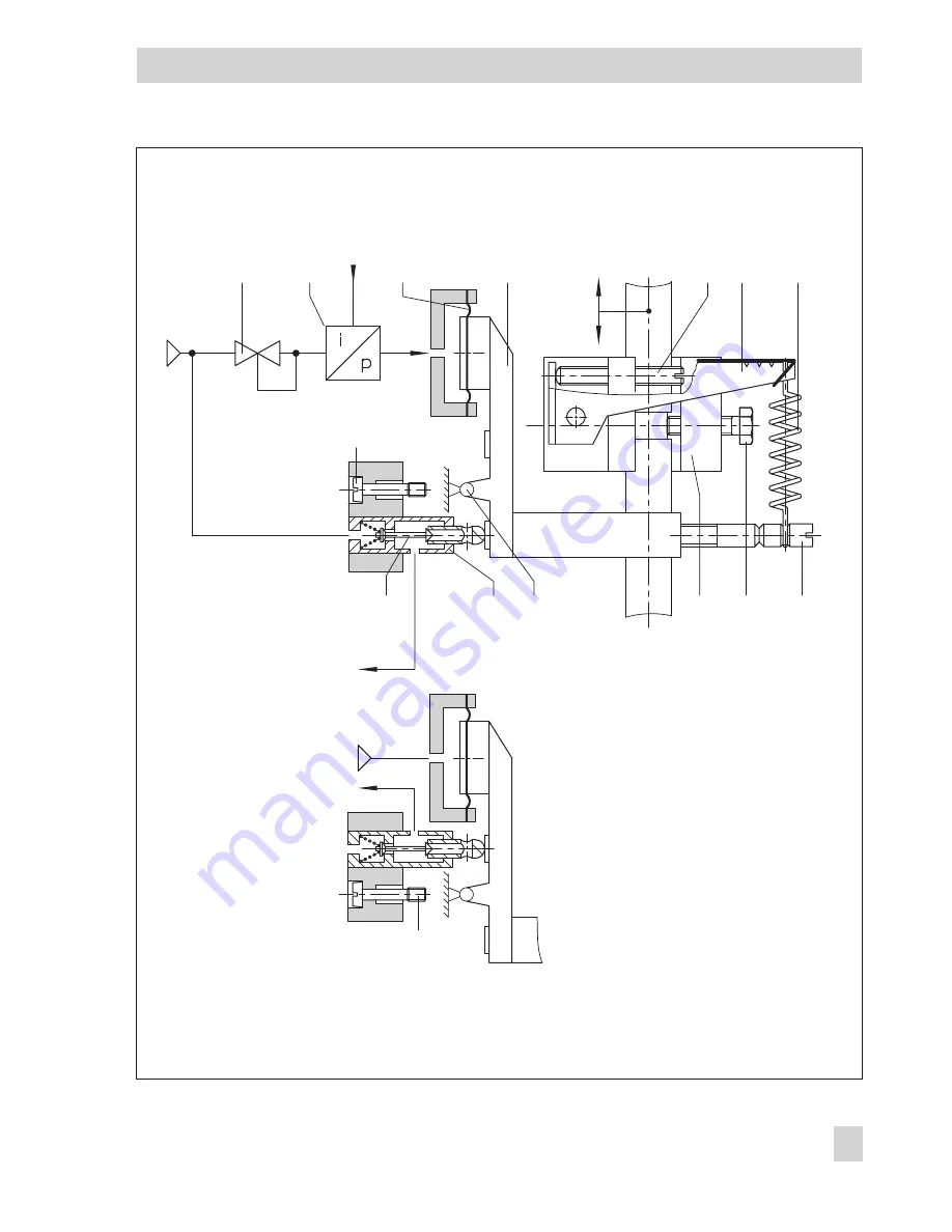
Design and principle of operation
Fig. 1 · Functional diagram
1
Supply
2
i
14
14
13
12 11
10
9
8
3
p
e
p
e
p
st
p
st
4
5 6
7
Span
Booster
direction of action >>
Booster
direction of action <>
Travel
Zero
1 Pressure regulator
2 i/p converter
3 Measuring spring
4 Diaphragm lever
5 Adjustment screw for
zero
6 Lever
7 Range spring
8 Adjustment screw for
span
9 Clamping screw
10 Clamp
11 Rotary axis
12 Booster
13 Double plug
14 Screw
Содержание 3760
Страница 24: ...24 EB 8385 EN ...
Страница 25: ...EB 8385 EN 25 ...
Страница 26: ...26 EB 8385 EN ...
Страница 27: ...EB 8385 EN 27 ...
Страница 28: ...28 EB 8385 EN ...
Страница 29: ...EB 8385 EN 29 ...
Страница 30: ...30 EB 8385 EN ...
Страница 31: ...EB 8385 EN 31 ...
Страница 32: ...32 EB 8385 EN ...
Страница 33: ...EB 8385 EN 33 ...
Страница 34: ...34 EB 8385 EN ...
Страница 35: ...EB 8385 EN 35 ...


