Samoa Industrial, S.A. - Box 103 Alto Pumarín – 33211 Asturias Spain – Tel. +34 985 381 488 – Fax. +34 985 384 163
IMPORTANT :
L’entretien de l’enrouleur doit être obligatoirement mené par un personnel spécialisé et suivant les
caractéristiques établies sur ce manuel.
•
Le système de blocage automatique s’active en tournant la bobine à 180º et se désactive en tirant légèrement sur
le flexible.
•
Toujours maintenir le flexible au moment de l’enrouler afin d’éviter tout risque de lésion ou de mauvais
fonctionnement.
•
Procéder à un contrôle périodique des unions et du flexible afin de garantir un bon fonctionnement du produit et
remplacer les pièces endommagées si nécessaire.
•
Lubrifier la rotule ainsi que l’axe en faisant passer l’huile par l’orifice hexagonal de la carcasse.
Wichtig:
Die Wartung kann nur von geschultem Personal gem. Dieser Bedienungsanleitung ausgeführt werden.
•
Der automatische Schlauchstopper funktioniert ab einer halben Umdrehung der Trommel und wird durch leichtes
Ziehen am Schlauch wieder gelöst.
•
Beim Aufrollen soll der Schlauch zur besseren Führung immer gehalten werden, um Fehlfunktionen des Aufrollers
und Beschädigungen am Schlauch zu verhindern.
•
Von Zeit zu Zeit sollten alle Halterungen und der Schlauch auf Beschädigungen und Verschleiss überprüft werden.
Ebenso die richtige Funktion des Aufrollers. Beschädigte Teile immer durch Original-Ersatzteile ersetzen.
•
Das Gelenk und die Achse werden mit Öl durch die sechseckige Öffnung im Gehäuse geschmiert.
WARNING:
Before carrying out the hose replacement, assure that the air supply is shut off, the hose is without
pressure and the spring is unloaded.
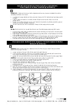
1. Unscrew and remove the swivel with a 28 mm wrench as showed in figure 4a.
2. Turn the hose reel upside down and insert a 14 mm hexagonal wrench to hold back the shaft. Loosen the two
screws (figure 4b) and gently turn the wrench clockwise to unload the spring.
3. Unscrew the four screws that hold the two covers together and remove the covers and the rollers support (figure
4c).
WARNING:
Do not open the spring housing. The spring must only be replaced by qualified staff.
4. Turn the drum upside down and remove the latch and the latch spring (figure 4d).
5. Put two screw drivers into the slots and lift out the lid (figure 4e).
6. Loosen the hose connection and replace the hose.
7. Connect a new hose to the drum, inserting it through the rollers support. Mount the hose stop at the desired
distance from the end.
8. Reassemble the hose reel reversing each step. Lubricate the latch and the drum bearing if necessary.
9. When the covers are assembled, insert the 14 mm hexagonal wrench and turn the wrench counter clockwise until
the hose stop reaches the roller support. Turn two more turns to load the spring.
10. Hold the hexagonal wrench firmly while fastening the two screws (figure 4f). Check the correct operation by
pulling out and rewinding it completely. Adjust the spring load if necessary. Lubricate and mount the swivel.
R05/04
850809
3
Hose replacement/ Sustitución de la manguera/ Comment remplacer le flexible/
Austausch des Schlauches
GB
F
Operation and maintenance/ Modo de empleo y mantenimiento/
Mode d’emploi et entretien/ Handhabung und Wartung
D


