Index revision : F - November 2017
22
7012
4. Diagram of the various fluid circuits
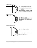
4.1. Paint diagram
N.B. All hoses are made of polyamide, except:
11-41 which are in PTFE, dimensions in mm.
Note: The PTFE hoses should never be replaced by polyamide hoses.
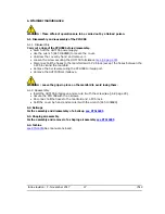
4.2. Bellcup and injector rinsing diagrams
N.B. All hoses are made of polyamide, except:
31-32 which are in PTFE, dimensions in mm.
WARNING : The rinsing cycle must end with a compressed air sequence, circuits 31,32 and 36
must be purged and dried before restarting the high voltage.
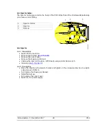
4.3. Microphone air diagram
N.B. All hoses are made of polyamide, dimen-
sions in mm.
11
Paint supply - Ø 4 x 6 PTFE
41
Dump - Ø 4 x 6 PTFE on 1,5 m then
Ø 7 x 10
51
Paint supply pilot - Ø 2,7 x 4
53
Dump pilot - Ø 2,7 x 4
31
Bellcup rinsing solvent / air - Ø 2,7 x 4
PTFE
32
Injector rinsing solvent / air - Ø 2,7 x 4
PTFE
56
Injector rinsing solvent / air pilot - Ø 2,7
x 4
58
Commande solvant/ air rinçage exté-
rieur bol - Ø 2,7 x 4
26
Microphone air - Ø 4 x 6
43
Microphone return - Ø 4 x 6
11
41
53
51
DES01309
PV32
PV31
DES04173
36
58
31
32
56
32
31

