background image


Index revision : D - March 2018

76

7115

13.14.  Appendices

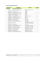
13.14.1.  Hose protection casing

This casing protects the hoses and cables, thereby guaranteeing flexibility and longevity.

13.14.2.  Gun protection cover

13.14.3.  Warning sign

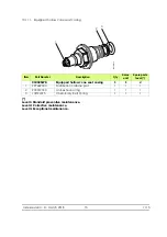
13.14.4.  Safety relief valve

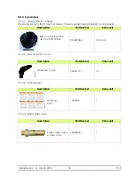
Description

Part Number

Sales unit


Rilsan hose protection 

duct with 30 collars

910021086

50-m roll

Description

Part Number

Sales unit


Protective cover 

900011711

10

Description

Part Number

Sales unit


Warning 


sign 

1407684

1

Description

Part Number

Sales unit


Safety relief valve 

6.5 bar 1/4 G

903080401

1

DES01269

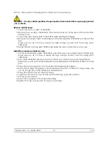
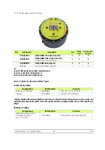
N˚ Sames 1407684

This sign must be hung in the booth.

Manual electrostatic equipment for the application of paint or varnish

• This equipment must only be used by SAMES trained personnel.

• The command module must be located at least 1,5m from the booth openings.

• The use of the command module must be completely dependent upon the running 
of the booth's exhaust fan.

• Regroup the cables and pipes arriving to the spray gun to prevent them from 
dragging on the ground where they could be severed.

• Only metallic recipients must be used for cleaning liquids. They must definitely be 
grounded.

• Use cleaning liquids with a flash point higher than ambient temperature.

• Correctly ground all of the metallic parts in the booth, as well as the parts to be 
painted.

• The operator and persons working nearby must wear antistatic shoes.

• The operator's hand must be in contact with the spray gun grip.

• Work on an antistatic floor such as bare concrete or a metallic grating.

• Switch off the command module for any maintenance operation, in particular for the 
cleaning of the nozzle and the cap, and for the rinsing of the paint circuit with the 
cleaning liquid.

• If the spray gun is equipped with a trigger lock, it must be engaged during the 
cleaning of the nozzle and the cap and during a prolonged stop.

• The electrostatic application equipment must be maintained on a regular basis and 
repaired according to the instructions in the manual.

WARNING

GB

WARNUNG

Elektrostatisches Handgerät zum Auftragen von Farben/Lacken von

• Dieses Gerät darf nur durch von SAMES ausgebildetem Personal bedient werden.

• Das Steuermodul ist mindestens 1,5 m von den Öffnungen der Kabine entfernt 
anzubringen.

• Die Inbetriebnahme des Steuermoduls muss vom Betrieb des Ventilators des 
Abzugs der Kabine abhängig sein.

• Zur Lackierpistole führende Kabel und Schläuche gruppieren, um zu vermeiden, 
dass diese auf dem Boden liegen, wo sie beschädigt werden können.

• Für Reinigungsflüssigkeiten sind ausschliesslich Metallbehälter zu verwenden. Diese 
müssen zuverlässig geerdet werden.

• Reinigungsflüssigkeiten mit einem Flammpunkt über der Raumtemperatur 
verwenden.

• Alle Metallteile der Kabine sowie die zu beschichtenden Werkstücke sachgemäss 
erden.

• Das Bedienungspersonal und Personal, das in unmittelbarer Nähe arbeitet haben 
antistatisches Schuhwerk zu tragen.

• Die Hand des Bedieners muss direkten Kontakt zum Griff der Pistole haben.

• Auf antistatischem Fussboden, wie roher Beton, oder Metallrostfussboden arbeiten.

• Vor Wartungsarbeiten ist das Steuermodul auszuschalten, insbesondere für die 
Reinigung der Düse, des Aufsatzes und zum Spülen des Lackkreislaufs mit 
Reinigungsmittel.

• Wenn die Lackierpistole mit einer Sicherheitssperrvorrichtung für den Abzug 
versehen ist, ist diese bei Reinigung de Düse, des Aufsatzes und einer längeren 
Unterbrechung zu verriegeln.

• Die elektrostatische Beschichtungsanlage ist regelmässig zu warten und unter 
Einhaltung der Anweisungen im Benutzerhandbuch zu reparieren.

Dieses Schild muss in der Kabine angebracht werden. 

DE

WAARSCHUWING

Elektrostatische handapparatuur voor applicatie van verf/vernis

• Dit apparaat mag alleen door SAMES opgeleid personeel worden gebruikt.

• De bedieningsmodule moet zich op minder dan 1,5m afstand van de 
cabineopeningen bevinden.

• De inwerkingstelling van de bedieningsmodule moet onderworpen zijn aan de 
inschakeling van de zuigventilator van de cabine.

• Groepeer de kabels en leidingen die bij het pistool uitkomen zodat ze niet over de 
grond slepen, waar ze kunnen worden afgesneden.

• Gebruik alleen metalen bakken voor de reinigingsvloeistoffen. Zij dienen op veilige 
wijze op de grond te worden gezet.

• Gebruik reinigingsvloeistoffen met een vlampunt dat hoger is dan de 
omgevingstemperatuur.

• Zorg voor een degelijke aardaansluiting van alle metalen cabine- onderdelen en alle 
verfbare delen.

• De gebruiker en het personeel in zijn nabijheid dienen antistatisch schoeisel te 
dragen.

• De hand van de gebruiker heeft direct contact met de kolf van het pistool.

• Werk op een antistatische grond zoals beton of een metalen rooster.

• Schakel de bedieningsmodule uit voor alle onderhoudshandelingen, vooral bij 
reiniging van de loop of de beschermkap en bij spoeling van het verfcircuit met de 
reinigingsvloeistof.

• Als het pistool is uitgerust met een trekkervergrendeling, dan dient u deze te 
gebruiken tijdens reiniging van de loop of de beschermkap en tijdens langdurige 
uitschakeling.

• De elektrostatische applicatieapparatuur dient regelmatig te worden onderhouden 
en gerepareerd volgens de aanwijzingen in de gebruikshandleiding.

Bevestig deze plaat in de cabine.

NL

ADVARSEL

Manuelt udstyr til elektrostatisk påføring af maling/lak

• Udstyret må kun anvendes af personale, der er uddannet af SAMES.

• Betjeningsmodulet skal være anbragt mindst 1,5m fra kabinens åbninger.

• Betjeningsmodulet må kun kunne tændes, når kabinens udsugningsventilator er i 
gang.

• Alle kabler og slanger, der er forbundet til pistolen, bør samles for at undgå, at de 
flyder på gulvet, hvor de risikerer at blive skåret over.

• Rengøringsvæskerne må kun opbevares i metalbeholdere. Disse skal være sikkert 
forbundet med jord.

• Der skal bruges rengøringsvæsker med et flammepunkt over stuetemperatur.

• Alle metalliske dele i kabinen såvel som emnet, der skal males, skal jordes korrekt.

• Operatøren og de personer, der arbejder i nærheden, skal bære antistatisk fodtøj.

• Operatørens hånd skal være i direkte berøring med pistolskæftet.

• Der skal arbejdes på et antistatisk underlag, såsom rå beton eller metalriste.

• Betjeningsmodulet skal sættes ud af drift inden al vedligeholdelse, specielt ved 
rengøring af dysen eller hætten og rensning af malingskredsløbet vha. 
rengøringsvæsken.

• Hvis pistolen er udstyret med en anordning til aflåsning af aftrækkeren, skal denne 
være slået til under rengøringen af dysen eller hætten og ved længerevarende 
standsninger.

• Udstyret til elektrostatisk påføring skal vedligeholdes regelmæssigt og repareres 
ifølge forskrifterne i brugsvejledningen.

Dette skilt skal være anbragt i kabinen. 

DK

VARNING

Manuell elektrostatisk utrustning för applikation av färg/lack

• Denna utrustning får endast användas av personal utbildad av SAMES.

• Manövermodulen skall vara belägen minst 1,5 m från hyttöppningana.

• Igångsättningen av modulen skall förutsätta inkoppling av hyttens utsugningsfläkt.

• Samla ihop kablar och slangar som går in på pistolen så att de inte ligger i vägen 
på golvet, där de riskerar att skäras av.

• Endast metallbehållare får endast för rengöringsvätskor. De skall jordas på säkert 
sätt.

• Använd rengöringsvätskor med en flampunkt som ligger över 
omgivningstemperaturen.

• Jorda på korrekt sätt alla metalliska delar av hytten, liksom de delar som skall 
målas.

• Operatören och personer som arbetar i närheten av de metalliska delarna skall 
bära antistatiska skodon.

• Operatörens hand skall vara i direkt kontakt med pistolkolven.

• Arbeta på ett antistatiskt golv av typ bar betong eller en metallisk gallerdurk.

• Koppla bort manövermodulen vid varje underhållsarbete, i synnerhet vid rengöring 
av munstycket, hatten och sköljningen av målningskretsen med rengöringsvätska.

• Om pistolen är utrustad med en avtryckarlåsning, skall denna vara ilagd vid 
rengöringen av munstycket, hatten och vid ett långvarigt stopp.

• Den elektrostatiska applikationsutrustningen skall underhållas regelbundet och 
repareras i enlighet med anvisningarna i användarmanualen.

Denna skylt skall placeras i hytten.

SE

VAROITUS

I n Käsikäyttöiset sähköstaattiset maalaus-/lakkausruiskut

• Laitteita saa käyttää vain SAMESin kouluttama henkilöstö.

• Ohjausmoduuli on sijoitettava vähintään 1,5 m päähän maalauskopin aukoista.

• Ohjausmoduulin toiminta on kytkettävä maalauskopin imutuulettimen 
käynnistymiseen.

• Katkeamisvaaran välttämiseksi maalausruiskun johdot ja letkut on sijoitettava siten, 
että ne eivät laahaa maata.

• Puhdistusaineille käytettävä ainoastaan metallisäiliöitä. Säiliöiden maadoitus on 
varmistettava.

• Käytettävä puhdistusaineita, joiden leimahduspiste on korkeampi kuin ympäristön 
lämpötila.

• Kaikkien maalauskopin metalliosien sekä maalattavan kappaleen asianmukaisesta 
maadoituksesta on huolehdittava.

• Laitteiston käyttäjän ja sen läheisyydessä työskentelevien on pidettävä antistaattisia 
jalkineita.

• Käyttäjän käden on oltava suorassa kosketuksessa maalauspistoolin peräosan 
kanssa.

• Työskentelytasona on oltava antistaattinen pinta, kuten paljas betoni tai metalliritilä.

• Ohjausmoduulista on katkaistava virta kaikkien huoltotoimien ajaksi, etenkin 
puhdistettaessa suutinta tai suojakupua ja huuhdottaessa maalikiertoa 
puhdistusnesteellä. 

• Jos pistoolissa on liipaisimen lukitustoiminto, sitä on käytettävä puhdistettaessa 
suutinta tai suojakupua ja laitteiston ollessa pitempään käyttämättä.

• Sähköstaattinen maalauslaitteisto on huollettava säännöllisesti ja korjaukset on 
tehtävä käyttöohjeiden mukaisesti.

Tämä kilpi on sijoitettava maalauskoppiin.

FI

DES00790

Содержание Nanogun Airmix

Страница 1: ...Index revision D March 2018 1 7115 User manual SAMES KREMLIN SAS 13 Chemin de Malacher 38240 MEYLAN FRANCE Tel 33 0 4 76 41 60 60 www sames kremlin com Nanogun Airmix and GNM 6080 versions LR HR MR...

Страница 2: ...ourses in the operation and maintenance of your equipment A catalogue is available on request Choose from a wide range of courses to acquire the skills or knowledge that is required to match your prod...

Страница 3: ...echnical characteristics 16 4 1 General characteristics of the guns 16 4 2 Flows 17 4 2 1 Versions without whip LR 17 4 2 2 Version with whip HR MR 18 4 3 Characteristics of the GNM 6080 19 4 4 Charac...

Страница 4: ...mon malfunctions and repairs 52 13 Spare parts 54 13 1 Nanogun Airmix guns for both high resistivity HR and low resistivity LR solvent based paints 54 13 1 1 120 bar version 55 13 1 2 200 bar version...

Страница 5: ...13 13 Options for Nanogun Airmix guns 75 13 14 Appendices 76 13 14 1 Hose protection casing 76 13 14 2 Gun protection cover 76 13 14 3 Warning sign 76 13 14 4 Safety relief valve 76 14 The various ver...

Страница 6: ...UE directive and for use in Zone 1 1 1 Version identification 1 1 1 On the gun barrel The marking on the barrel is the same across the entire Nanogun Airmix line 1 1 2 On the lower part of the gun han...

Страница 7: ...safety standard i e Standard EN13849 level SIL 1 maintaining this level of safety requires periodic inspections of the equipment at least once every 5 years or 15 000 hours of operations which ever c...

Страница 8: ...N 1 GROUP D HAZARDOUS LOCATIONS when connected to model GNM 6080 power supply unit The Nanogun Airmix gun has been designed to operate within a 2nd degree pollution envi ronment as defined according t...

Страница 9: ...he parts to be painted The resistance relative to the ground must be less than or equal to 1M for a 500 V voltage measurement This resistance must be regularly checked and in any case at least once a...

Страница 10: ...ded equipment downtime Verify the good working order of the paint hose prior to any equipment start up The electro pneumatic link connector secured by means of two screws MUST NEVER BE DIS CONNECTED W...

Страница 11: ...nozzle have not been correctly remounted onto the gun Never soak or immerse the gun in the solvent The operator is able as needed to use a cloth soaking in solvent in order to clean the gun and then i...

Страница 12: ...to con tact with the materials listed below Stainless steel Fluoro Ethylene Propylene FEP Polyamide Imide PAI Polyoxymethylene POM Tungsten carbide and tungsten PTFE elastomer Polypropylene IXEF Glass...

Страница 13: ...is gun The switch Rep 1 allows turning on or off the high voltage supply When this switch is placed in position I activating the trigger turns on the high voltage When this switch is placed in positio...

Страница 14: ...al generator defaults If it is impos sible to acknowledge this default the problem would require a service call by the repairs department please contact SAMES KREMLIN 1 Maintenance indicator light 2 H...

Страница 15: ...of the high voltage cascade Maintenance indicator light This indicator light turns on orange once the trigger has been pulled 800 000 times or after 1 000 hours of gun operations see 10 1 page 28 Thi...

Страница 16: ...e 45 V AC maximum Input current of the high voltage cascade 300 mA maximum Air coupling 1 4 NPS F Paint coupling 1 2 JIC F Paint resistivity 10 M cm 500 M cm Version QD high resistivity 0 5 M cm 500 M...

Страница 17: ...220 290 380 21 04 11 220 290 380 25 04 13 220 290 380 29 06 09 330 430 570 21 06 11 330 430 570 25 06 13 330 430 570 29 06 15 330 430 570 33 09 09 450 590 770 21 09 11 450 590 770 25 09 13 450 590 77...

Страница 18: ...ec and up to 80 sec the flow loss is around 20 to 25 Note for higher viscosities and very long hoses above certain limits the flow starts to fall sud denly and becomes almost zero Resistivity limitati...

Страница 19: ...a temperature of 20 C 68 F at atmospheric pressure General Mass 1 7 kg Space requirements Diameter 168 mm Height 91 mm Operating temperature 0 40 C GNM 6080 input Voltage 88 264 V AC Frequency 50 60...

Страница 20: ...nsor serves to activate the high voltage power supply once the air valve returns to a value lying between 1 and 1 8 mm The button located in back of the gun does not serve to adjust the paint flow rat...

Страница 21: ...017 White Vaseline 100 ml 1 1 H1GSYN037 Dielectric grease for the high voltage cascade and nozzle needle channel 100 ml 1 1 Part Number Designation Qty Sales unit 900010160 Cartridge and air valve ass...

Страница 22: ...m R 304DA Facom Ref SAMES KREMLIN 240000095 Flat wrenches 5 5 5 11 15 17 18 21 24 27 Pipe wrench 4 13 Flat pliers Cutting pliers Part Number Designation Qty Sales unit 900016773 Supply pad removal too...

Страница 23: ...Index revision D March 2018 23 7115 6 1 Use of the multipurpose wrench 1 Clamping of the air cap ring 2 Extraction of the head nozzle DES06546 1 DES06505 2...

Страница 24: ...or the 200 bar version and the pump s air inflow must be equipped with a safety relief valve to limit pressure to a maximum value of 6 5 bar 1 Overall air supply 2 Air cleaner 3 Primary air valve 4 Pu...

Страница 25: ...sity e g 120 seconds or more may be projected as well 8 1 2 Resistivity Use a paint whose resistivity is adapted to the Nanogun Airmix gun version that you own The optimal resistivity range lies betwe...

Страница 26: ...addition of more air serves to reduce the impact width by 25 at a 120 bar pressure more over the higher the product pressure the smaller the influence being exerted by the additional air In order to l...

Страница 27: ...e hoses and electrical cable in a space where vehicles circulate preventing the risk of them being crushed or severed It is prohibited to spray a liquid other than paint or varnish using the Nanogun A...

Страница 28: ...ing Seal cartridge J3STKL005 1 3 months O ring chemically inert J3STKL014 1 6 months O ring FEP Viton J2FENV435 1 12 months O ring chemically inert J3STKL078 2 12 months O ring chemically inert J3STKL...

Страница 29: ...paint circuits are no longer pressurised Dump the paint circuit 10 2 Electro pneumatic coupling Step 1 Unscrew the 7 10 air hose coupling nut using a 16 flat wrench not mandatory for Step 3 Step 2 Di...

Страница 30: ...1 flat wrench unscrew the upper nut on the paint hose and then finish the unscrewing manually while holding the lower nut Step 4 Verify the presence of the O ring on the paint nut Verify the presence...

Страница 31: ...2 With a 21 flat wrench unscrew the upper nut on the paint hose Unscrew the nut while turning the hose For the reassembly step screw the upper nut on the paint hose until reaching its stop point Posi...

Страница 32: ...Step 1 With the multipurpose wrench P N 900012843 unscrew the air cap ring Step 2 Extract the head nozzle using the multipurpose wrench Do not use your fingers If necessary replace the head seal For...

Страница 33: ...her do not use the housing where the centering pin is located Make a slight turning motion with the screwdriver and proceed in the same man ner with the second housing Remove the washer by hand The re...

Страница 34: ...de equipped with its small PTFE tube Step 1 If necessary clean the electrode manually and with precaution with a drill or metal rod of 1mm diameter Step 2 Insert the electrode equipped with the PTFE t...

Страница 35: ...r and the metal end of the electrode The usually measured value is of the order of 200 to 300 but a value up to 1000 is admissible Step 5 Fold the electrode with the flat pliers and cut to about 5 mm...

Страница 36: ...s in place while double checking their correct location and after coating them first with Vaseline Step 2 Seal cartridge Unscrew the cartridge using the tool P N 900010160 Should the ring and external...

Страница 37: ...damage the resistance during its extraction 10 7 Paint nozzle needle Step 1 Unscrew the paint nozzle needle in back of the gun recover the spring Step 2 Press on the trigger and pull it manu ally tow...

Страница 38: ...into its housing Coat the retaining screw with LOCTITE low strength thread lock and then clamp the screw so that the switch shows slight resist ance 10 9 Trigger Step 1 Using a screwdriver unscrew the...

Страница 39: ...t nozzle needle see 10 7 page 37 Step 2 Unscrew the air valve stop nut using an 18 flat wrench Point the gun barrel upwards and recover the spring and air valve Should the parts not fall tap in the pa...

Страница 40: ...the air valve body they may however be destroyed The conical seal must be pushed down into its locking mechanism on the valve body in being sure not to alter its conic range Level 2 If the air valve...

Страница 41: ...r to adjust the reed sensor position proceed step by step without adding multiple washers at the same time WARNING Various washer thicknesses may be installed always begin by adding or removing the th...

Страница 42: ...tion wires then carefully pull the contacts towards the back Step 4 Unscrew the high voltage contact in front of the barrel with a flat screwdriver Extract the cascade WARNING Be mindful of the colour...

Страница 43: ...the back Step 4 Replacement of the O rings of both air channels and the air valve step 3 not required Remove and replace the three O rings Step 5 Replacement of the barrel handle o rings step 3 manda...

Страница 44: ...eal every 12 months Step 5 Remove the electrical connector by pushing it to a point where the base exits Replace the connector joint every 12 months Step 6 Replacement of the base unscrew the ground w...

Страница 45: ...dry contact 0 5 A max 24 V AC DC max A Pink Primary transformer HVU 3 B Shield Shield C White REED sensor trigger D Yellow Dallas chip E Brown 0 V joint chip reed F Third party shield G Green Primary...

Страница 46: ...d Step 1 Unplug the GNM 6080 control module Step 2 Depressurise the gun s air circuit Step 3 Drain the gun s paint circuit and rinse it using an appropriate solvent see 2 4 page 11 Step 4 Depressurise...

Страница 47: ...nect the air and high voltage supplies Engage the safety catch on the trigger Step 2 Loosen the cap nut retrieve the cap and the low cone and plunge them into a solvent bath for a few minutes then cle...

Страница 48: ...ernal thread of the barrel with dielectric grease Step 8 Put the internal cone and the cap back in place Tighten the cap nut 11 4 Elimination of wastes The removal transport and elimination of wastes...

Страница 49: ...material containing glass fibre PTFE stainless steel 4 PEEK tungsten carbide PTFE stainless steel 5 PEEK chemically inert rubber stainless steel 7 PTFE 8 Brass agglomerated carbon 9 Stainless steel ch...

Страница 50: ...astic material containing fibre 24 Plastic material chemically inert rubber 25 28 Aluminium 27 29 Rubber 30 Plastic material containing fibre copper stainless steel 33 Fibre joint 37 Polyamide not loa...

Страница 51: ...nd electronic components ROH printed circuit 5 Bottom sheet metal and fastening screws Steel 6 Connector card Electrical and electronic components ROH printed circuit 7 Electrical power supply Electri...

Страница 52: ...e paint hose The paint is con stantly flowing Foreign body preventing the nozzle needle from closing Disassemble the seat casing clean it along with the seat Clean the nozzle needle tip Worn nozzle ne...

Страница 53: ...ooks Verify the grounding of parts and the con veyor Excessive ventilation Reduce the booth s suction flow rate while respecting current regulations Spraying pressure too high Reduce the spraying pres...

Страница 54: ...Index revision D March 2018 54 7115 13 Spare parts 13 1 Nanogun Airmix guns for both high resistivity HR and low resistivity LR solvent based paints DES06509 1 3 2 4...

Страница 55: ...page 60 1 1 1 3 130001435 Air cap see 13 1 5 page 60 1 1 3 4 130001420 Nozzle see 13 1 3 page 59 1 1 1 Not shown 050123306 Adapter M1 2 JIC F3 8NPS paint hose 1 1 3 Item Part Number Description Qty Sa...

Страница 56: ...e 7 5 m 1 1 910021070 150 Nanogun Airmix 120 bar HR JP with nozzle 09 091and paint hose 15 m 1 1 910021070 300 Nanogun Airmix 120 bar HR JP with nozzle 09 091and paint hose 30 m 1 1 Nanogun Airmix gun...

Страница 57: ...435 Air cap see 13 1 5 page 60 1 1 3 4 130001420 Nozzle see 13 1 3 page 59 1 1 1 Not shown 050123306 Adapter M1 2 JIC F3 8NPS paint hose 1 1 3 Item Part Number Description Qty Sales unit Spare parts l...

Страница 58: ...7 5 m 1 1 910025957 150 Nanogun Airmix 200 bars HR JP with nozzle 09 091and paint hose 15 m 1 1 910025957 300 Nanogun Airmix 200 bars HR JP with nozzle 09 091and paint hose 30 m 1 1 Nanogun Airmix gu...

Страница 59: ...le MX09 131 Option 130001423 Nozzle MX09 151 Option 130001424 Nozzle MX12 091 Option 130001425 Nozzle MX12 111 Option 130001426 Nozzle MX12 131 Option 130001427 Nozzle MX12 151 Option 130001428 Nozzle...

Страница 60: ...tenance Level 3 Exceptional maintenance Item Part Number Description Qty Sales unit Spare parts level 910019358 Fitted air cap ring 1 1 1 1 900013829 HP nozzle protection 1 1 3 2 900010164 PTFE flat s...

Страница 61: ...Index revision D March 2018 61 7115 13 2 Nanogun Airmix gun DES06513 2 3 8 9 10 11 12 14 17 18 23 24 25 26 19 20 27 28 29 30 31 33 34 35 36 8 13 37 38 16 21 22 13 36 1 4 5 15 20 32 6 7...

Страница 62: ...1 1 3 13 900010385 C M4 curved washer head screw 4 1 3 14 900013808 PTFE flat washer included in item 15 1 1 2 15 910018204 On off handle with o ring and magnet included in item11 1 1 3 16 J3STKL005...

Страница 63: ...ressure 30 129670405 Rotating air coupling option 1 3 31 250000037 Base handle fastening screw 2 1 3 32 900010605 55 elbow 1 1 3 33 250000214 Elbow fastening screw 1 1 3 34 910022663 Trigger pin lock...

Страница 64: ...ber Description Qty Sales unit Spare parts level 910019359 Equipped seat casing 1 1 1 1 J3STKL046 O ring chemically inert 1 1 1 2 900013368 Anti extrusion ring 1 1 1 3 900012300 Anti extrusion ring 1...

Страница 65: ...ales unit Spare parts level 910019514 Equipped barrel 1 1 3 1 910015881 Seal cartridge 1 1 1 2 900012782 Anti extrusion ring included in Rep 1 1 1 1 3 J3STKL005 O ring chemically inert included in Rep...

Страница 66: ...the magnet is lost contact SAMES KREMLIN Item Part Number Description Qty Sales unit Spare parts level 910018203 Equipped air valve 1 1 3 1 900010256 Sealing ring 1 1 1 2 J3STKL005 O ring chemically i...

Страница 67: ...U brass nut 1 1 3 Item Part Number Description Qty Sales unit Spare parts level 910015869 100 10 m electro pneumatic coupling 1 1 3 910015869 200 20 m electro pneumatic coupling 1 1 3 910015869 300 3...

Страница 68: ...Qty Sales unit Spare parts level 1 910019204 075 Black 7 5 m HR product hose 5 1 1 1 910019204 150 Black 15 m HR product hose 5 1 1 1 910019204 300 Black 30 m HR product hose 5 1 1 1 2 050450605 Produ...

Страница 69: ...nd the product hose 13 9 2 For Nanogun Airmix LR guns Level 1 Standard preventive maintenance Level 2 Corrective maintenance Level 3 Exceptional maintenance Item Part Number Description Qty Sales unit...

Страница 70: ...Description Qty Sales unit Spare parts level 1 910025953 075 Product hose MR 7 5 m 5 1 1 1 910025953 150 Product hose MR 15 m 5 1 1 1 910025953 300 Product hose MR 30 m 5 1 1 1 2 910025541 Whip HP 4...

Страница 71: ...Barrel 1 160000041 Chemically inert O ring Handle 1 160000067 Red FKM O ring Handle 1 J2FTCF018 Black FKM O ring Air nipple 2 J3STKL018 Chemically inert O ring Air nipple 1 J4BRND039 Fiber seal Handl...

Страница 72: ...llow cone kit K50 1 1 3 910025480 60 Hollow cone kit K60 1 1 3 910025480 70 Hollow cone kit K70 1 1 3 1 900011505 Cap 1 1 2 2 910018917 Spraying cone 1 1 2 3 910025472 Injector 20 hollow cone 1 1 1 91...

Страница 73: ...ce Level 2 Corrective maintenance Level 3 Exceptional maintenance Item Part Number Description Qty Sales unit Spare parts level 910025478 Equipped hollow cone seat casing 1 1 2 1 999469300 Distributio...

Страница 74: ...move the cap Install the round spray hollow cone 1 Put the flat seal in place Ref 900014821 and the hollow cone adaptor Ref 900011504 Make sure you do not lose or break the high voltage contact and th...

Страница 75: ...e pump must be equipped with a M 1 2 JIC output cou pling Rotating coupling Item Part Number Description Qty Sales unit Spare parts level 910017193 GNM 6080 CE control module 1 1 3 910017192 GNM 6080...

Страница 76: ...ton of een metalen rooster Schakel de bedieningsmodule uit voor alle onderhoudshandelingen vooral bij reiniging van de loop of de beschermkap en bij spoeling van het verfcircuit met de reinigingsvloei...

Страница 77: ...X LR 120b lg 7 5 EU 910021114 072 Equipement Nanogun MX LR 120b lg 7 5 US 910021114 15 Equipement Nanogun MX LR 120b lg 15 EU 910021114 152 Equipement Nanogun MX LR 120b lg 15 US 910021114 30 Equipeme...

Страница 78: ...LR 120b lg 30 EU 910021114 30 X X X X Equipment Nanogun MX MR 120b lg 7 5 EU 910025958 07 X X X X Equipment Nanogun MX MR 120b lg 15 EU 910025958 15 X X X X Equipment Nanogun MX MR 120b lg 30 EU 91002...

Отзывы: