


Operator’s manual
Double-sided mower with central
suspension
“REWERS”
- 23 -
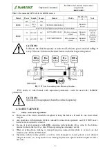
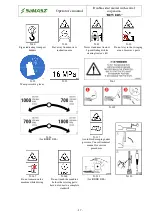
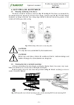
CAUTION:
Use the machines with PTO shafts designed to drive them. Before the work
begins, check the safety guards (in tractor, mower and PTO shaft), if they are
placed correctly and are not damaged. Damaged or lost parts must be
replaced with genuine ones. Make sure the PTO shaft is properly mounted. It
is forbidden to approach the rotating parts, because it may lead to serious
injuries or even death. All service and repair operations must be done only
after the tractor engine has been stopped and ignition key off, all rotating
parts have come to the complete standstill and the cutterbar is on the ground.
Before the operation begins, read operator’s manuals of both the machine
and PTO shaft.
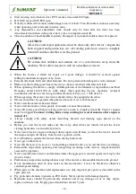
CAUTION:
When changing the tractor, with which the machine operates, control the
length of PTO shaft again, as otherwise the machine can be damaged.
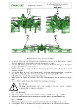
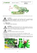
5.3.
Control panel (for mowers with controller)
CAUTION:
To provide correct control of the machine when in operation, it is necessary
to enable the floating section of distributor which the main hydraulic system
of the machine is connected to.
Mower’s control is performed with use of one of tractor’s hydraulic sections and control panel
located in tractor’s cabin. Action to be performed is chosen by operator with buttons on the panel
and then carried out by means of tractor's hydraulics. To enable control, press the power switch
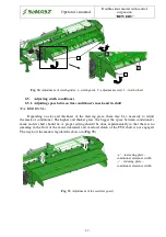
(
Fig. 22
) and push button (
1
)
(
Fig. 21
). Pushing the button is signalled with diode (
23
) above
the button.
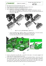
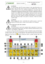
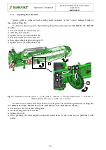
Fig. 21.
Control panel – functions
4
3
3
5
6
14
15
16
17
18
19
20
21
22
13
12
11
10
9
8
7
2
1
23