background image

2. Product Specifications


SAM4S ER-5100II SERIES 


2-3 

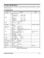
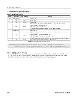
2-3 Printer(M-U420) Specification 

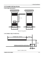
2-3-1 Printer Specification 

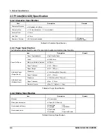
Item Description 

Remark 

Model 

 M-U420 


Print Method 

 Serial Impact Dot Matrix   


Total number of dots 

 9 Dots (Vertical)   


Printing Format 

Dot Pitch 

 Vertical 

: Approx. 0.35 mm 

 Horizontal   

: Approx. 0.35 mm 


Printing Speed 

 3.0 Line/sec 

DC24V, 25


Printing Direction 

 Bi-directional 


Feeding Method 

 Friction Feed 


Line Spacing 

 Approx. 4.3 mm 


Paper Feeding 

Intermittent Fast Feed 

 Only Receipt Paper 


Power Voltage 

 24.0VDC +5%, -10% (Min 21.6VDC) 

Head / Motor 

Power Supply Volt 

Circuit Input Voltage 

 5V 

±

5% 

Sensor 

Number of wire(Dot) 

 9 Dots 


Wire Diameter 

 Approx. 0.29mm 


Dot Pitch 

 Approx. 0.35mm 


Character Height 

 Approx. 3.1mm 


Printer Head 

Resistance 

 Approx. 19.2 

 At 

25


Head Temperature 

 Thermal Sensor (Tama Elec LP310-1J) 


Sensor 

Sensor 

 Timing(Encoder) / Home / Validation 

3 pcs 

Life 

 8,000,000 Lines 


MCBF 

 4,000,000 Lines 


Reliability 

Printer Head Life 

 300,000,000 Dot / Wire 


Dimension (mm) 

150.7(W) 

×

273.5 (D) 

×

110.6 (H) 


Weight 

 Approx. 1Kg 


Table2-2 Thermal Printer Specification 


Содержание ER-5100 II SERIES

Страница 1: ...Specifications 3 Installation and Operation 4 Disassembly and Assembly 5 Alignment and Adjustments 6 Troubleshooting 7 Exploded Views and Parts List 8 PCB Layout and Parts List 9 Block Diagram 10 Wir...

Страница 2: ...this part component Indicates the part or component is an electro statically sensitive device Use caution when handling these parts Acronym Definition ASIC Application for Specific Integrated Circuit...

Страница 3: ...anual may not in whole or in part be copied photocopied reproduced translated or converted to any electronic or machine readable from without prior written permission of Shin Heung Precision SAM4S ER...

Страница 4: ...troubleshooting All information in this manual is subject to change without prior notice Therefore you must check the correspondence of your manual with your machine No part of this manual may be copi...

Страница 5: ...rwise damaged should be replaced with parts that meet the original specifications Always determine the cause of damage or over heating and correct any potential hazards 6 Observe the original lead dre...

Страница 6: ...rument s ground lead to the instrument chassis ground before connecting the positive lead always remove the instrument s ground lead last 1 3 Precautions for Electrostatically Sensitive Devices ESDs 1...

Страница 7: ...32C Flow Control DTR DSR H W Flow Control Baud Rate 9600 Bps Connector DB9P Female I F PBA Voltage Supply VCC 5V 200mA supplies at 9Pin of Connector Printer Model EPSON M U420 Print Speed 3 0 Line sec...

Страница 8: ...mensions 2 2 1 Appearance Dimensions mm Figure2 1 Dimensions 2 2 2 Location Feature Figure2 2 Location Feature Printer Cover Key Board Drawer Customer 10 Digits VFD Display Operator Display 10 Digits...

Страница 9: ...g Approx 4 3 mm Paper Feeding Intermittent Fast Feed Only Receipt Paper Power Voltage 24 0VDC 5 10 Min 21 6VDC Head Motor Power Supply Volt Circuit Input Voltage 5V 5 Sensor Number of wire Dot 9 Dots...

Страница 10: ...escription Remark Paper Type standard High Quality Paper Width 44 5 0 5mm Maximum Outside Diameter 83 0mm Paper Thickness 0 06 0 09mm Paper Roll Spec Paper Weight 52 3 64 0 g Dimension 135 210mm W X 7...

Страница 11: ...oduct Specifications SAM4S ER 5100II SERIES 2 5 2 3 Printer M U420 Specification 2 3 5 Printing Specification Figure2 3 Printing pattern 2 3 6 Validation Paper Printable Area Figure2 4 Validation patt...

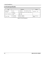
Страница 12: ...t Voltage Current U S A AC 120V 60Hz Min 102V Max 138V Europe AC 220V 240V 50Hz Min 195 5V Max 264 5V Max Min 15 Power Consumption Regularity Approx 20W Peak Approx 30W Output Voltage AC 19V 2 3A Wire...

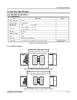
Страница 13: ...S 5 C N 8 C P N I P 9 E D I S t r o h S n i P 8 6 n i P 7 4 R S D 6 C N 7 D X T 3 R T D 4 E L A M G F C N 1 E L A M D B N O R C E E L A M E F R O T C E N N O C D X R 2 G S 5 C N 8 R C E N I P 9 E D I...

Страница 14: ...st can receive a data SPACE Logic0 The host can not receive a data The ECR transmits a data to the host or receipt printer after confirming this signal 9 VCC Output VCC 5V 200mA is supplied at 9Pin of...

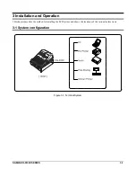
Страница 15: ...0II SERIES 3 1 3 Installation and Operation This chapter describes the method for installing the ECR system and shows the locations of the various feature items 3 1 System configuration Figure 3 1 Ter...

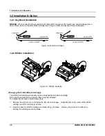
Страница 16: ...allation Figure 3 7 Ribbon Cassette Changing the Printer Ribbon Cartridge The ER 5100II receipt journal printer uses a replaceable ink ribbon cartridge Once print becomes faint a new ink ribbon must b...

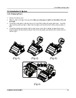
Страница 17: ...o load the receipt paper push the green lever on the left to release the paper feed rollers Insert the paper into the printer as shown in fig 2 Push the paper until it exits the front of the printer a...

Страница 18: ...ur host computer 3 2 5 Options No Item Description Remark 1 Water Proof 2 Dust Cover 3 Memory SRAM 4MBITs 4MBITs 1 Factory Option On Main PBA 4 Fiscal Function Fiscal B d Control Chip Factory Option O...

Страница 19: ...ions Mode Accessible Position Remark VOID Void Off Register REG Manager X REG Off Register REG X Off Register REG Manager X Z Off Register REG Manager X Clear Totals Z PGM Void Off Register REG Manage...

Страница 20: ...160 key 90 key or 60 key as shown in Table 3 5 Figure 3 5 Keyboard ex ER 5115II Model Keys Type ER 5100 160 Rubber Flat ER 5140 90 Membrane Raised ER 5115 60 Membrane Raised Table 3 5 Keyboard Type SB...

Страница 21: ...ll programs and totals to be erased and to be default Note Service Mode is not marked in a mode painting part Service Mode spins the Mode Key once just in a Program Mode to the right direction And nee...

Страница 22: ...rear VFD display 3 3 6 3 Test Key Board 1 Press Press 2 and CASH key on key board 2 Press any key you want on the key board 3 The key code of pressed key will be showed on the VFD 4 Turn the mode swi...

Страница 23: ...he MAIN BOARD D 2 Page7 11 4 Lift off the ASS Y CASE UPPER B from the ASS Y CASE LOWER E Page7 1 7 2 4 1 2 Ass y VFD Display 1 Separate the WINDOW DISPLAY B 7 from the ASS Y CASE UPPER B Page7 1 7 3 2...

Страница 24: ...age7 5 7 11 7 Separate the HOLDER PRINTER C 8 from the CASE LOWER D 19 Page7 5 7 11 4 2 2 Ass y Clerk Key 1 Lift up the ASS Y CLERK KEY D 25 and the COVER CLERK KEY D 26 or COVER FRONT D 24 from the A...

Страница 25: ...onents in this ECR 5 1 Adjustment Procedure Figure 5 1 Adjustment Procedure Slide the Reset signal adjustment plate on the Guide frame to the left or right as necessary so that skew a is within the ra...

Страница 26: ...5 Adjustments and Adjustments 5 2 SAM4S ER 5100II SERIES MEMO...

Страница 27: ...Ok Y 1 Check the Bridge Diode BD2 on Main PBA 2 Check the VDISP signal whether it is short N Power 24V Ok Power VCC 5V Ok Y 1 Check the Fuse FU1 on Main PBA 2 Check the Bridge Diode BD1 on Main PBA 3...

Страница 28: ...EPROM 1 Check the LM393 U24 2 Check the Power 24V 5V 3 Check the related Circuit and Pattern on PCB N N SRAM Ok Y Y N CPU Ok Y N 1 Check the nCS nRD nWR signal of SRAM 2 Check the VBT Battery Volt 3...

Страница 29: ...ATA Signal CPU P1 7 3 Check the LATCH Signal CPU P1 6 4 Check the Harness Disconnect Ok Power VDISP VCC Ok Y 1 Refer to the Power Problem 2 Check the Harness 1 Check the Harness 2 Check the VFD Discon...

Страница 30: ...nal PR4 PR5 3 Check the related Circuit and Pattern STA471 Q11 4 Check the printer harness 5 Replace the printer Y N Printing Trig OK 1 Check HEAD_TRIG signal CPU W1 2 Check the related Circuit and Pa...

Страница 31: ...8 3 Check the related Circuit and Pattern 4 Check Change Key Board Assy 5 Check the KBD Connector on PBA Specific Key Failure 1 Check the affected Key 2 Check the Matrix Bus Data Bus 3 Check the Diode...

Страница 32: ...he SELF TEST in the S MODE using the Loop Back test Connector 2 Check the connection of the RS 232C Connector and Loop Back Connector 3 Check the TXD RXD DTR DSR Pin on CPU 4 Check the MAX232 Driving...

Страница 33: ...ADD CHECK operation must be performed E 6 Indicates that the cash declaration operation must be performed E 7 Indicates that EAT IN TAKE OUT DRIVE THRU procedure must be performed before tendering E 8...

Страница 34: ...6 Troubleshooting 6 8 SAM4S ER 5100II SERIES MEMO...

Страница 35: ...SAM4S ER 5100II SERIES 7 1 7 Exploded Views and Parts List 7 1 Main Set 7 1 1 Exploded View Figure7 1 TOTAL DISASSEMBLY...

Страница 36: ...1 Main Set Figure7 2 ASS Y COVER PRINTER A ASS Y COVER PRINTER No Parts No Description Specification Q ty Design Location Serviceable Remark A 1 JK72 20210A PMO COVER VALIDATION 1 Y A 2 JK72 20211A P...

Страница 37: ...7 Exploded View and Parts List SAM4S ER 5100II SERIES 7 3 7 1 Main Set Figure7 3 ASS Y CASE UPPER...

Страница 38: ...000172 SCREW TAPPING 3 Y JK72 40356A PMO WINDOW DISPLAY ER 5100II STD 1 Y JK72 40356B PMO WINDOW DISPLAY ER 5115II 5140II STD 1 Y JK72 40356D PMO WINDOW DISPLAY ER 5140IIF SEPOL 1 Y JK72 40356E PMO W...

Страница 39: ...7 Exploded View and Parts List SAM4S ER 5100II SERIES 7 5 7 1 Main Set Figure7 4 ASS Y PRINTER...

Страница 40: ...ty Design Location Serviceable Remark C 1 JK73 40201A RMO PRINTER 4 Y C 2 6002 000209 SCREW TAPPING 4 Y C 3 JK59 20006A UNIT PRINTER 1 Y C 4 6006 000199 SCREW ASS Y TAPTITE 1 Y C 5 6002 000174 SCREW...

Страница 41: ...7 Exploded View and Parts List SAM4S ER 5100II SEIRES 7 7 7 7 7 1 Main Set Figure7 5 M U420 PRINTER...

Страница 42: ...20045A PAPER TAKE UP BELT F701009020 1069905 1 Y 120 JK81 20045B GEAR DECELERATION CARRIAGE 1028031 1 Y 121 JK81 20045C GEAR TRANSMISSION 1028009 1 Y 122 JK81 20045D GEAR DECELERATION 1028011 1 Y 123...

Страница 43: ...81 20046N VALIDATION STOPPER PLATE 1028036 1 Y 508 JK81 20046P VALIDATION GUIDE 1028044 1 Y 509 510 JK81 20046Q C B P TITE SCREW 3X10 F ZN 3C 1282378 1 Y 511 JK81 20046R DRIVEN PLATE SUB ASS Y 1028539...

Страница 44: ...3 JK81 20048B E RING 2 5 F UC 3C 1283654 1 Y 544 JK81 20048C GEAR PAPER FEED 1028038 1 Y 545 JK81 20048D GEAR PAPER EXTENSION SHAFT 1028054 1 Y 546 JK81 20048E PAPER HOLD ROLLER F750255020 1065200 1 Y...

Страница 45: ...7 Exploded View and Parts List 7 11 SAM4S ER 5100II SERIES 7 1 Main Set Figure7 6 ASS Y CASE LOWER...

Страница 46: ...74 SCREW TAPPING 2 Y D 12 6006 000187 SCREW ASS Y MACHINE 1 Y JK39 10002A CBF POWER CORD AUSTRALIA 1 Y JK39 10003A CBF POWER CORD USA 1 Y JK39 10008A CBF POWER CORD UK 1 Y D 13 JK39 10501A CBF POWER C...

Страница 47: ...Figure7 7 Drawer 4B 8C b2 b1 b11 b12 b5 b3 b4 b7 b8 b6 b9 c ASS Y HOUSING e ASS Y BOTTOM d ASS Y LOCK b ASS Y TRAY TILL b10 e1 e5 e2 e3 e4 e7 e6 e8 d1 d2 d3 d4 d11 d6 d7 d9 d10 d5 d8 c2 c1 c3 a8 a4 a...

Страница 48: ...COIN A TYPE 7B8C 1 Y a 1 6002 000175 SCREW TAPPING PWH 2 M3 L8 ZPC YEL 3 Y a 2 JK70 00068A IPR HOLDER PLATE A TYPE SBHG 1 T1 2 1 Y a 3 JK72 00083A PMO BILL PARTITION A TYPE HIPS BLK 5 Y a 4 JK72 00082...

Страница 49: ...VER 1 N d 4 JK75 00027B MEC LOCK LEVER A TYPE 2 LATCH SHORT LEVER 1 N d 5 6107 001014 SPRING ES 0 4 D4 8 L18 1 Y d 6 JK33 10500A SOLENOID DC A DRAWER 1 Y d 7 6001 000131 SCREW MACHINE BH 2 M3 L6 ZPC Y...

Страница 50: ...7 Exploded View and Parts List SAM4S ER 5100II SEIRES 7 16 7 3 Key Board Key Board 60Key Figure7 10 Key Board 60 Key...

Страница 51: ...10 JK72 40327A AS KEY TOP L 1 1 1 Y F 11 JK61 70301A AS RETURN SPRING 1 2 1 Y F 12 JK72 40324A PMO HOLDER HOOK A 1 Y F 13 JK70 10382A IPR SPACER KEYBOARD 1 Y F 14 JK72 40325A PMO HOLDER HOOK B 1 Y F 1...

Страница 52: ...7 Exploded View and Parts List SAM4S ER 5100II SEIRES 7 18 7 3 Key Board Key Board 90Key Figure7 11 Key Board 90 Key...

Страница 53: ...F 12 JK72 40324A PMO HOLDER HOOK A 1 Y F 13 JK70 10382A IPR SPACER KEYBOARD 1 Y F 14 JK72 40325A PMO HOLDER HOOK B 1 Y F 15 JK72 40312A PMO FRAME KEYBOARD 1 Y F 16 6002 000175 SCREW TAPPING 12 Y F 17...

Страница 54: ...Description Specification Q ty Design Location Serviceable Remark F JK59 30016A UNIT KEYBOARD RUBBER FLAT 160KEY 1 Y F 1 JK73 20216A REX WATER PROOF 1 Y F 2 JK68 40012A LABEL P KBD SHEET 1 Y F 3 JK81...

Страница 55: ...7 Exploded View and Parts List 7 21 SAM4S ER 5100II SERIES MEMO...

Страница 56: ...SAM4S ER 5100II SERIES 8 1 8 PCB Layout and Parts List 8 1 Main PCB...

Страница 57: ...DETECTOR M51953BL TF0J DIP 5P 18V 1 U21 Y 2001 000119 R CARBON 680OHM 5 1 4W AA TP 2 4X6 4MM 1 R176 Y 2005 001001 R WIRE WOUND 0 1ohm 5 1W WRIT1W0 1 J 1 R160 Y 2301 000010 C FILM PEF 100nF 5 100V TP 1...

Страница 58: ...1 L3 Y 0401 001003 DIODE SWITCHING MMBD6050LT1 70V 200mA 22 28 D1 D21 D28 D29 D30 D32 D41 D42 D43 Y 0402 001189 DIODE RECTIFIER M4 400V 1A SMD 2 TP 6 D33 D37 D40 Y 0404 001051 DIODE SCHOTTKY SK14 40V...

Страница 59: ...91 R168 N 2008 000054 R CHIP 36KOHM 5 1 10W 1608 2 R98 R163 N 2008 000057 R CHIP 56KOHM 5 1 10W 1608 1 R161 N 2008 000060 R CHIP 68KOHM 5 1 10W 1608 4 R114 R116 R117 R128 N 2008 000072 R CHIP 680KOHM...

Страница 60: ...cation Serviceable Remark JK92 01460A PBA I F ER 5100II 232 1 STD 1 ASS Y Y 3701 000232 CONNECTOR DSUB 9P 2R FEMALE ANGLE AUF 1 CN1 Y 3711 004108 WAFER BOX HEADER 1R 6P 2 5mm STRAIGHT 1 CN2 Y JK39 405...

Страница 61: ...NESS ML 80 JUMPER AWG22 52mm SIL 18 JP1 JP18 Y 2202 000630 C CERAMIC MLC AXIAL 100nF 10 50V X7R TP 2 C1 C2 Y 3711 004111 WAFER BOX HEADER 1R 8P 2 5mm ANGLE 1 CN1 Y 3711 002002 CONNECTOR HEADER BOX 22P...

Страница 62: ...00 5200 10G 1 ASS Y Y JK39 40002A CBF HARNESS ER 220N UL1061 400MM BLK R 1 TURRET TO DISP Y JK07 00005A DISPLAY VFD DC10G FUTABA 10 LT 50GK 1 10 DIGIT Y 3711 002812 CONNECTOR HEADER BOX 11P 1R 2mm ST...

Страница 63: ...cription Specification Q TY Design location Serviceable Remark JK92 01227B PBA SUB POWER SW ER 5200 STD 1 ASS Y Y 3711 000190 CONNECTOR HEADER 1WALL 2P 1R 7 92mm ST 1 CN3 Y 3711 000829 CONNECTOR HEADE...

Страница 64: ...50V X7R TP 1 C1 Y JK39 00009C CBF HARNESS FISCAL ER 5115IIF 34P 1 Y JK41 10575A PCB FISCAL 2M FR 4 2L T1 6mm 164 132mm 1 FISCAL PCB N 8 6 1 FISCAL 2MBIT EPROM 27C2001 No Part No Description Specifica...

Страница 65: ...8 PCB Layout and Parts List 8 10 SAM4S ER 5100II SERIES MEMO...

Страница 66: ...CPU GPIO UART D 7 0 nCS AUX 3 nCS AUX 2 nCS AUX 4 30V VDI VF MODE CLERK KEY 74HC541 RTC IC RS5C372A 32 768KHZ SRAM 1 SRAM 2 DECODER 2MBIT 1MBIT BOOT EPROM SRAM 1 RXD TXD DTR DSR CS 16C542 2 CS FISCAL...

Страница 67: ...9 Block Diagram 9 2 SAM4S ER 5100II SERIES MEMO...

Страница 68: ...AL VPRT 24V DRAWER 2 CN18 DRAWER 2 SIGNAL COMP SIG COMP SIG DRAWER 1 SIGNAL CN18 DRAWER 1 VDISP AC VDISP AC SIGNAL VPRT AC GND TXD0 RXD0 SIGNAL VSERIAL CLERK 2 CLERK 1 SIGNAL CLERK 4 VFD SCLK VFD LAT...

Страница 69: ...10 Wiring Diagram 10 2 SAM4S ER 5100II SERIES MEMO...

Страница 70: ...FD Display Drawer Block Page 11 6 6 UART RS 232 Block Page 11 7 7 Printer M U420 Sensor Page 11 8 8 Printer M U420 Head Motor Page 11 9 9 Fiscal Logic Block Page 11 10 10 Fiscal Voltage Block Page 11...

Страница 71: ...A16_ROM R99 100 INT1_PRTTIMING RXD0 KBD 2 KBD 5 22pF C67 220pF C65 R126 3 3K Size A3 File Name ER 5100II Rev 13 12 74HC14 U20 F MMBD6050LT1 D30 VDD50V CE1 100uF 16V VDD50V C44 100nF MMBD6050LT1 D29 4...

Страница 72: ...M A16 P1 1 0x00000 0x2FFFF EPROM A16 A17 CPU 0x0000 0xFDFF 0x10000 0x1FDFF 0x20000 0x2FDFF 0x300000 0x3FDFF CS_SRAM 2_BUF X1 32 768KHZ Sheet 0x0000 0xFDFF 0x10000 0x1FDFF ER 5100II MAIN SCH VDD50V R62...

Страница 73: ...39 R43 MMBD6050LT1 D19 39 R45 MMBD6050LT1 D20 39 R47 MMBD6050LT1 D21 39 R49 D11 MMBD6050LT1 R30 39 D1 MMBD6050LT1 R32 39 MMBD6050LT1 D2 39 R34 File Name CLERK 2 CLERK 3 iBUTTON DALLAS KEY 1 CN5 1 CON...

Страница 74: ...2222A Q5 R133 100 22uF CE5 50V 1uF C48 R87 4 7K 100nF C55 3 4 74HC14 U20 B INT0_PFAIL LOW ACTIVE R129 1K 470pF C64 VBAT D28 MMBD6050LT1 270 R61 1 CN11 A 2 CN11 B C A3 ER 5100II MAIN SCH 12 Sheet R90 1...

Страница 75: ...DISPLAY_CLK Serial Clock VDISP 30V VDISP R119 4 7K 10K R120 VPRT24V D36 M4 4 Date A3 Y H O REV1 2 B C VFD DISPLAY BLOCK VDD50V VDISP_ON R140 10K 1 3 2 Q10 KSA708 Y 2 3 1 Q12 MMBT2222A 3 CN13 3 6 CN13...

Страница 76: ...DATA 14 CN20 N 7 CN20 G 8 CN20 H 2 CN20 B 5 CN20 E 6 CN20 F 12 CN20 L 13 CN20 M 11 CN20 K R174 4 7K MAIN B D 20 CN20 T 18 CN20 R 19 CN20 S 17 CN20 Q TITLE ER 5100II Sheet 12 SERIAL VOLTAGE SUPPLY VSE...

Страница 77: ...8 74HC14 U20 D 11 10 74HC14 U20 E R83 4 7K C38 100nF R74 4 7K INT1_PRTTIMING EPSON VREF 2 047 V 34 CN12 AH 33 CN12 AG 31 CN12 AE 30 CN12 AD 28 CN12 AB 27 CN12 AA File Name AUTOCUT STATUS RESETHOME STA...

Страница 78: ...K R135 1K DRAWER 2_OUT DRAWER 1_OUT PRT_FEEDSOL_ROUT PRT_FEEDSOL_JOUT HEAD_DOT1_OUT HEAD_DOT7_OUT HEAD_DOT5_OUT HEAD_DOT9_OUT PRT_STAMP_OUT HEAD_DOT8_OUT HEAD_DOT6_OUT HEAD_DOT2_OUT PRT_STAMP_OUT PRT_...

Страница 79: ...5 FD 6 FD 4 FD 2 FD 3 FD 1 FD 0 FD 7 FD 5 FD 6 FD 4 FD 2 FD 3 FD 1 FD 0 FD 0 7 FA 14 FA 13 FA 11 FA 10 FA 8 FA 6 FA 5 FA 3 FA 2 FA 0 FA 0 17 A 1 CS_FISADDH_WR CS_FISADDL_WR FISCAL LOGIC BLOCK VDD50V...

Страница 80: ...D 2 OE_FISCAL_EPROM 470 R21 470 R25 VFIS_ONOFF ER 5100II ER 5100II MAIN SCH A D 2 4 D B C 2 T6 4 7K R60 T11 T10 20 CN7 T 14 CN7 N 32 CN7 AF 26 CN7 Z 19 CN7 S 13 CN7 M 31 CN7 AE 25 CN7 Y FA 9 FA 13 FA...

Страница 81: ...VSERIAL VBAT MEMORY BACK UP VOLTAGE VDISP VFD DISPLAY GRID VOLTAGE LOGIC VOLTAGE VPRT24V FU1 250V 3 15A 5V POWER BLOCK R161 56K HEATSINK_S HS1 MMBD6050LT1 D43 MMBD6050LT1 D42 2 3 1 MMBT2222A Q20 2K R...

Страница 82: ...1 H 5 CN1 E 6 CN1 F 2 CN1 B 3 CN1 C VFD_DISPCISCON SHORT 10P AN YEONHO ER 5200 KENYA VFD_STORBE VFD_LATCH VFD_SCLK VFD_SDIN ER 5240 kenya Back light VF ER5200FRONTVFD SCH File Name ER 5200 5240 DISPLA...

Страница 83: ...Size ER5200REARVFD SCH TITLE D 1 Sheet 2 P5 VCC VCC Date A3 2002 10 28 D V1 0 Drawn by 4 3 1 2 CN1 B 3 CN1 C 5 CN1 E 6 CN1 F 8 CN1 H 9 CN1 I 11 CN1 K 2 CN2 B 5 CN2 E 4 CN2 D 8 CN2 H 7 CN2 G 10 CN2 J...

Страница 84: ...ERIAL 1 2 2 3 MAX232 ADD DATA MAIN B D SERIAL I F B D CPU UART MAIN B D SERIAL I F B D DSR0_IN 4 CN2 4 DTR0_OUT RXD0_IN TXD0_OUT 1 CN2 1 ER 5100II SERIAL DEFAULT SCH File Name 9 CN1 I 6 CN1 F 3 CN1 C...

Страница 85: ...me POWER SWITCH PCB POWER CORD AC 230V 50Hz POWER ON OFF SWITCH TITLE Sheet POWER SW PCB SCH 1 1 4 3 4 D 2 EARTH BROWN BLUE RED BLUE 3 4 B C Date A3 2005 09 12 POWER SWITCH PCB K W CHOI 1 CON BOX 2P 6...

Страница 86: ...me 2 9 5 1 BLU PC5 25 21 17 13 PA1 PA4 PA7 PC2 PB2 PB5 3 33 29 33 4 B C 1 6 2 10 FIS_A17 PA6 PA4 PA3 PA2 PA0 PA7 BLK 26 22 18 FIS_VPP PB4 PB6 14 GND PB0 PC1 PC5 PA0 PC4 PC1 PC3 PC6 PB7 PB4 PA4 34 2M_V...

Страница 87: ...11 18 SAM4S ER 5100II SERIES MEMO...

Страница 88: ...page to record any special servicing information such as Service Bulletins or Supplements When possible record changes to Code numbers directly on the actual Parts List Always record Service Bulletin...

Страница 89: ...Shin Heung Precision April 2006 Printed in KOREA V1 0 Code No JK68 70111A...

Отзывы: