

SAM4S ER-5100II SERIES
4-1
4 Disassembly and Assembly
Caution:
·
Before installation, be sure to turn off the power switch.
·
Use gloves to protect your hand from being cut by the angle and the chassis.
·
Connect all the cables correctly. When connecting or disconnecting the cables, be careful not to apply
stress to the cables. (It may cause disconnection)
·
Be careful not to bind interface cables and AC power cord together.
Note:
Before disassembling, first of all separate the ASS'Y CASE UPPER(B) from the ASS'Y CASE LOWER(D).
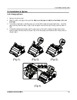
4-1 Disassembling the Case Upper Block
4-1-1 Ass’y Case Upper
1. Open the ASS'Y COVER PRINTER(A ) and lift it off. (Page7-1,7-2)
2. Remove the four screws(B-6:3pcs,B-11:1pcs) from the ASS'Y CASE LOWER(E). (Page7-3,7-11)
3. Separate the two harnesses(
ⓑ
,
ⓒ
) from the MAIN BOARD(D-2). (Page7-11)
4. Lift off the ASS'Y CASE UPPER(B) from the ASS'Y CASE LOWER(E). (Page7-1,7-2)
4-1-2 Ass’y VFD Display
1. Separate the WINDOW DISPLAY(B-7) from the ASS'Y CASE UPPER (B). (Page7-1,7-3)
2. Separate the FRONT DISPLAY BOARD(B-14) from the ASS'Y CASE UPPER(B). (Page7-1,7-3)
3. Separate the two harnesses (
ⓐ
,
ⓒ
) from the FRONT DISPLAY BOARD(B-14). (Page7-3)
4-1-4 Ass’y Rear VFD Display
1. Separate the ASS'Y TURRET(B-10 ~ B-10) from the ASS'Y CASE UPPER (B). (Page7-1,7-3)
2. Separate the WINDOW TURRET(B-10) and the VFD DISPLAY BOARD(B-9)
from the ASS'Y TURRET.
(Page7-1,7-3)
4-1-5 Ass’y Cover Mode Switch
1. Separate the ASS'Y COVER MODE S/W(B-1 ~ B-5) from ASS'Y CASE UPPER(B). (Page7-1,7-3)
2. Remove the two screws(B-5) on the ASS'Y COVER MODE S/W(B-1 ~ B-5)
and separate the ASS'Y
SWITCH ROTARY(B-2 ~ B-4) from the COVER MODE S/W(B-1). (Page7-1,7-3)
3. Remove the two screws(B-2) on the ASS'Y SWITCH ROTARY(B-3 ~ B-4) and separate the BRKT MODE
SWITCH(B-3) and the SWITCH ROTARY (B-4). (Page7-1,7-3)
Содержание ER-5100 II SERIES
Страница 26: ...5 Adjustments and Adjustments 5 2 SAM4S ER 5100II SERIES MEMO...
Страница 34: ...6 Troubleshooting 6 8 SAM4S ER 5100II SERIES MEMO...
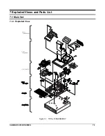
Страница 37: ...7 Exploded View and Parts List SAM4S ER 5100II SERIES 7 3 7 1 Main Set Figure7 3 ASS Y CASE UPPER...
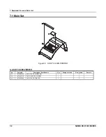
Страница 39: ...7 Exploded View and Parts List SAM4S ER 5100II SERIES 7 5 7 1 Main Set Figure7 4 ASS Y PRINTER...
Страница 41: ...7 Exploded View and Parts List SAM4S ER 5100II SEIRES 7 7 7 7 7 1 Main Set Figure7 5 M U420 PRINTER...
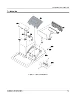
Страница 45: ...7 Exploded View and Parts List 7 11 SAM4S ER 5100II SERIES 7 1 Main Set Figure7 6 ASS Y CASE LOWER...
Страница 55: ...7 Exploded View and Parts List 7 21 SAM4S ER 5100II SERIES MEMO...
Страница 56: ...SAM4S ER 5100II SERIES 8 1 8 PCB Layout and Parts List 8 1 Main PCB...
Страница 65: ...8 PCB Layout and Parts List 8 10 SAM4S ER 5100II SERIES MEMO...
Страница 67: ...9 Block Diagram 9 2 SAM4S ER 5100II SERIES MEMO...
Страница 69: ...10 Wiring Diagram 10 2 SAM4S ER 5100II SERIES MEMO...
Страница 87: ...11 18 SAM4S ER 5100II SERIES MEMO...
Страница 89: ...Shin Heung Precision April 2006 Printed in KOREA V1 0 Code No JK68 70111A...