SAM4S ER-5100II SERIES
5-1
5 Alignment and Adjustments
This chapter describes the methods for aligning and adjusting components in this ECR.
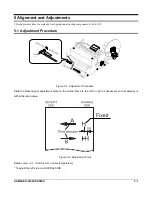
5-1 Adjustment Procedure
Figure 5-1. Adjustment Procedure
Slide the Reset signal adjustment plate on the Guide frame to the left or right as necessary so that skew(a) is
within the rated value.
Figure 5-2. Adjustment Point
Rated value : (a)
≤
1dot (0.4mm, normal temperature)
* To adjust the left side on JOURNAL SIDE.
Содержание ER-5100 II SERIES
Страница 26: ...5 Adjustments and Adjustments 5 2 SAM4S ER 5100II SERIES MEMO...
Страница 34: ...6 Troubleshooting 6 8 SAM4S ER 5100II SERIES MEMO...
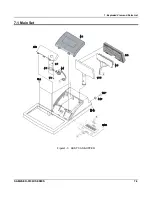
Страница 37: ...7 Exploded View and Parts List SAM4S ER 5100II SERIES 7 3 7 1 Main Set Figure7 3 ASS Y CASE UPPER...
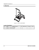
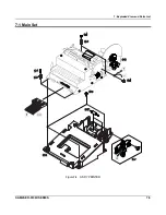
Страница 39: ...7 Exploded View and Parts List SAM4S ER 5100II SERIES 7 5 7 1 Main Set Figure7 4 ASS Y PRINTER...
Страница 41: ...7 Exploded View and Parts List SAM4S ER 5100II SEIRES 7 7 7 7 7 1 Main Set Figure7 5 M U420 PRINTER...
Страница 45: ...7 Exploded View and Parts List 7 11 SAM4S ER 5100II SERIES 7 1 Main Set Figure7 6 ASS Y CASE LOWER...
Страница 55: ...7 Exploded View and Parts List 7 21 SAM4S ER 5100II SERIES MEMO...
Страница 56: ...SAM4S ER 5100II SERIES 8 1 8 PCB Layout and Parts List 8 1 Main PCB...
Страница 65: ...8 PCB Layout and Parts List 8 10 SAM4S ER 5100II SERIES MEMO...
Страница 67: ...9 Block Diagram 9 2 SAM4S ER 5100II SERIES MEMO...
Страница 69: ...10 Wiring Diagram 10 2 SAM4S ER 5100II SERIES MEMO...
Страница 87: ...11 18 SAM4S ER 5100II SERIES MEMO...
Страница 89: ...Shin Heung Precision April 2006 Printed in KOREA V1 0 Code No JK68 70111A...

