background image

26

SALICRU

alarm will beep 1 sec. The equipments of the par-

allel system will shift to «Bypass mode».


ˆ

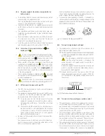
Shift the equipment or equipments to manual bypass 

as follows:

1. 

Remove the mechanical lock from bypass manual 

switch from switchgear panel and turn it «On».

2. 

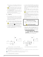
Remove the manual bypass switch cover, located 

in the rear side of the UPS and turn it to «BYPASS» 

position.

In parallel systems proceed in the same way in all 

the equipments.


ˆ


 Keep in mind that on «Bypass mode» or with the 

manual bypass switch on «BYPASS» position, 

the loads will remain exposed to the voltage and fre-

quency fluctuations from mains, blackouts and power 

outages, so it was possible choose a day with the lowest 

failure probability (days with no fluctuations, days with 

no storms,...) and speed up the process. 


ˆ

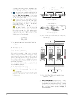
Turn the input circuit breaker switch of the equipment 

to «Off».

In parallel systems proceed in the same way in all the 

equipments.


ˆ

Turn all the input and output circuit breakers of the 

switchgear panel to «Off».

The system is completely shutdown and out of service 

and loads are supplied by means of the manual bypass 

switchgear panel.

Make the needed maintenance tasks.

6.3.2.  Shifting to normal mode.


The procedure to shift from maintenance bypass to normal 

mode is the same for single unit and parallel system,  less 

in the quantity of actions to make:


ˆ

 In case of handling the switches in the different 

order as the stated, 

it will break the power 

supply to the loads and even can cause damage 

to the UPSs.


ˆ

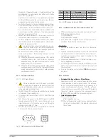
Turn the input and output circuit breaker switches from 

switchgear panel to «On».


ˆ

Turn the input switch of the own equipment to «On».

In parallel systems proceed in the same way in all the 

equipments.


ˆ

Turn the manual bypass switch, located in the rear side 

of each equipment to «UPS» position and put back their 

protection covers.

In parallel systems proceed in the same way in all the 

equipments.


ˆ

Turn the manual bypass switch of the switchgear panel 

to «Off» and put back its mechanical lock.


ˆ

In order to avoid wrong handling, the mechan-

ical lock, protection covers of the manual by-

pass and their fixing screws have to put back.


ˆ

For a single equipment.


Press the start up   key for more than 0.5 sec, the 

acoustic alarm will beep 1 sec. The equipment will 

start up.


ˆ

For a parallel system.


Press the start up   key for more than 

0.5 sec. in all UPSs and each one of them will be 

started up, finally the parallel system will be on 

«Normal mode».


ˆ

Load or loads are protected by the parallel system 

again.

6.4.  PARALLEL SYSTEM OPERATING


To operate with parallel systems, in order to avoid prob-

lems, check that the output 2 of each UPS is set to the same 

parameter in all of them.


The operating described hereafter, is for equipments with 

the standard setting preset from factory.


Check that the load or loads and/or the output circuit 

breaker switches are turned «Off». 


Turn the input circuit breaker switches from switchgear 

panel or manual bypass to «On» and the own input switches 

in each UPS too.

The UPSs supply AC voltage by means of their internal 

static bypass of each unit. Check if any alarm has been trig-

gered in the LCD panel. Measure the output voltage at the 

output terminals of each UPS separately, in order to check 

if the voltage difference is lower than 1 V among them. In 

case the voltage difference is higher than 1 V, check the 

wiring and the previous installation instructions.


If the difference voltage is lower than 1 V, press over the 

start up   key for more than 0.5 seconds in all UPSs and 

each one of them will be started up and all the UPSs will  

shift to «Normal mode». 

Measure the output voltage a the output terminals of each 

UPS separately, in order to check if the voltage difference is 

lower than 0.5 V among them. In case the voltage difference 

is higher than 1 V, the UPSs must be set (contact with the  

T.S.S.

).


Continue with the procedure if everything is correct only. 

Press the start up   key for than 0.5 sec. in all UPSs and 

each one of them will be shutdown.

Turn all the output switches from switchgear or manual by-

pass panel to «On». The output terminals of the switchgear 

panel will be supplied by means of the internal static by-

pass of the equipment.


Press the start up   key for more than 0.5 sec. in all UPSs and 

each one of them will be started up and all the UPSs will  

shift to «Normal mode».


Start up the load or loads.


Do not leave one of the UPSs with no neutral con-

nection as regard to the rest one. The neutral of all 

UPSs must be joined among them, either through the input 

or through the output. Do not open the input and output 

circuit breakers of the switchgear panel of one UPS at the 

same when the parallel system is turned On, otherwise the 

UPS can be damaged and the loads will be shutdown.

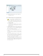
6.5.  HOW UPGRADE THE PARALLEL SYSTEM WITH A 

NEW UPS OR DOWNGRADE TO SINGLE MODE.


To do this manoeuvring, the parallel system must have a 

manual bypass panel for a parallel system.

In case of not having it, it has to  be foreseen a complete 

shutdown of the system and loads connected to it.


The steps here stated are to add an equipment in a parallel 

system of two units. To upgrade a single unit to a parallel 

Содержание 4.. 20 kVA series

Страница 1: ...SLC TWIN PRO2 4 20 kVA UNINTERRUPTIBLE POWER SUPPLY UPS USER S MANUAL...

Страница 2: ...nparts 5 2 CONNECTION 5 2 1 ConnectionoftheinputterminalstoACpowersupply 5 2 2 Connectionofload stotheoutputterminalsoroutput1 5 2 3 Connection of the load s to the output terminals 2 TWIN 3 PRO2from8...

Страница 3: ...5 OPERATINGMODES STATUSDESCRIPTION 7 6 WARNINGCODES 7 7 ERROROFAULTCODES 7 8 WARNINGINDICATORS 8 MAINTENANCE WARRANTY AND SERVICE 8 1 BATTERYMAINTENANCE 8 1 1 Notestoreplaceandinstallthebatteries 8 2...

Страница 4: ...sonnel exclusively Although we have made every effort to guarantee a com plete and accurate information in this user s manual we are not responsible for any errors or omissions that may exist The imag...

Страница 5: ...er s manual allows the end user to make any operating of both installation and commissioning in an easy and ordered way without doubt Finally once the equipment is commissioned and in operation it is...

Страница 6: ...ADVERTENCIA SLC TWIN PRO2 4 20 kVA This is a category C3 UPS product This is a product for commercial and industrial application in the second environment installation re strictions or additional mea...

Страница 7: ...ent will always prevail In the nameplate of the equipment the most important parameters and features can be checked Proceed with the installation accordingly StandardandB1 from4to10kVA Singlephaseinpu...

Страница 8: ...rent sharing signal under the cover Smart Slot Bat connector cover Battery connector StandardandB1 from8to10kVA Threephaseinputandsinglephaseoutput Digital input output RS232 USB EPO Manual bypass scr...

Страница 9: ...protection Battery module size 1 with 3x20 batteries and 50 A protection Battery fuses Terminal cover IEC inlet for AC power supply Terminal cover Battery switch Protection breaker Battery module siz...

Страница 10: ...10 SALICRU Battery switch Terminal cover Battery module size 2 with 4x20 batteries and 100 A protection Fig 3 Rear view of the battery module...

Страница 11: ...ording to Salicru s code 3 Quantity of batteries in one string 2x Quantity of strings in parallel Omitted for only one 0 Battery module with no batteries but with the needed accessories to fit them in...

Страница 12: ...to the worst conditions of input mains Wide input voltage range frequency range and wave shape so it is avoided the excessive use of the battery which has limited energy Available battery charger up...

Страница 13: ...r which is ac cepted by the main manufacturers of software and hardware The connection of the UPS with the SNMP is internal mean while the connection between the SNMP and the IT network is done by mea...

Страница 14: ...otect it against pos sible mechanical impacts dust dirt etc The equipment packaging has wooden pallet cardboard or wooden enclosure depending on the requirements ex panded polystyrene corners plastic...

Страница 15: ...e distances as the same UPS enclosure It is recommended to leave 75 cm additional free in each side for the possible tasks of the T S S or the needed power cable length to facilitate the movement of t...

Страница 16: ...hes which are only available in some models or equipments with extended back up times Ignore those operations related with your unit in case it does not have them Regarding the installation instructio...

Страница 17: ...lectrical regulations of the destination country The switches RCD and circuit breaker of a three phase input equipment connected to an IT power distribution system must break the NEUTRAL apart from th...

Страница 18: ...f the stated one in the UPS namopete 3 Relay for power contactor power supply 2 with 400V AC coil and NO contact type of 5A 1A minimum For parallel systems each equipment must have its own Backfeed pr...

Страница 19: ...mportant to pay attention to the following consideration Bonding PE stud U output phase Output neutral Main PE stud Input neutral R phase input Bonding PE stud U phase output 1 Output neutral 1 U phas...

Страница 20: ...lso the battery modules have protection and in this case they are doubled Once are internal by means of fuses and not ac cessible by the end user and the second ones by means of a two poles circuit br...

Страница 21: ...lly closed NC so it will open the electrical circuit when pressing it By means of the communication software the inverse func tion can be set Less particular cases it is better to not use this type of...

Страница 22: ...ructure N means the minimum quantity of equipments that the total load needs X means the quantity of redundant equipments that is to say the quantity of faulty UPSs that the system can allow at the sa...

Страница 23: ...both ports RS232 and USB at the same time Tab 4 shows the pin out of the RS232 signal in the DB9 female connector The RS232 is a serial data port so an important amount of information can be sent thro...

Страница 24: ...the risk of a long power outage for the first operating hours must be evaluated because the back up time of the UPS will be lower Do not start up the equipment and loads before section 6 states it Ne...

Страница 25: ...After a few seconds the UPS will be on Battery mode so it has to be considered their charge level the remaining back up time and the risk that means to operate on this operating mode If the AC mains i...

Страница 26: ...allel system again 6 4 PARALLEL SYSTEM OPERATING To operate with parallel systems in order to avoid prob lems check that the output 2 of each UPS is set to the same parameter in all of them The operat...

Страница 27: ...ear panel to On Turn the input circuit breaker switches from each UPS to On Turn the internal manual bypass switch of each UPS to UPS position The output switches of each UPS from switchgear panel mus...

Страница 28: ...erating mode as Frequency Converter With this operating mode the static bypass is disabled Tab 5 Control panel keypad functions The UPS has a control panel which has the following parts Four buttons w...

Страница 29: ...onnected at the output in by means of four segments which are equivalent to the following proportion 0 25 26 50 51 75 and 76 100 Information of the programmable outputs P1 It indicates that the progra...

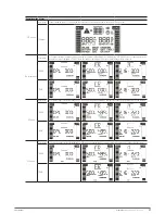
Страница 30: ...e R R Phase R S S Phase S T T Phase T Tab 9 Abbreviations shown in the LCD 7 4 SETTINGS IN THE LCD CONTROL PANEL Parameter 1 Parameter 2 Parameter 3 Fig 28 Parameter layout in the LCD panel Parameter...

Страница 31: ...MOD BAT setting YES Output voltage setting SI 18 Battery capacity and quantity of strings setting SI 19 Back up time setting SI Tab 10 Code list for parameter 1 Description and setting depending on th...

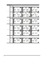
Страница 32: ...Code 04 TWIN PRO2 TWIN 3 PRO2 Bypass frequency range Fig 33 Parameter 2 setting Minimum limit of the acceptable input frequency range When the nominal frequency is 50 Hz the setting range is from 46 t...

Страница 33: ...fting Bypass shifting is understood as that one that the end users make it over the own UPS I e when pressing the OFF key at the front of the equipment when it is on normal mode then the load is shift...

Страница 34: ...11 2 to 13 6 V If the battery voltage is lower than the entered figure the program mable output will be shutdown The preset factory figure is 11 2 V Code 12 TWIN PRO2 Hot standby function enable dis...

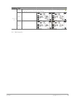
Страница 35: ...e is from 0 to 9 9 V and the preset factory figure is 0 V Code 15 TWIN 3 PRO2 Inverter voltage setting Fig 49 Parameter 2 setting Select Add or Sub to set the inverter voltage Parameter 3 setting The...

Страница 36: ...Parameter 2 setting It allows setting the battery capacity Parameter 3 setting It allows setting the MOD BAT quantity Code 19 TWIN 3 PRO2 Back up time setting Fig 54 Parameter 3 setting It allows sett...

Страница 37: ...e inverter on or when shutdown it The UPS does not supply output voltage The acoustic alarm beeps every two minutes TWIN 3 TWIN AC mode Description If the input voltage is inside the range the UPS wil...

Страница 38: ...me which will depend on their capacity also the acoustic alarm beeps every 4 sec TWIN 3 TWIN Bypass mode Description When the input voltage is inside the preset range and the bypass is enabled when th...

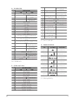
Страница 39: ...n error or fault the inverter will be blocked And the fault code will be displayed in the LCD panel and the icon will light Table 13 shows the error or fault codes and their description TWIN 3 TWIN Ta...

Страница 40: ...rvoltage 03 DC bus undervoltage 04 Unbalanced DC bus 06 Converter overcurrent 11 Inverter soft start fault 12 High inverter voltage 13 Low inverter voltage 14 Inverter output short circuited 1A Negati...

Страница 41: ...layed in the LCD panel Try to solve the problems by following the steps described in table 15 If the problem persists consult with our Technical Ser vice and Support T S S When necessary contact with...

Страница 42: ...rature is very high Check the fans and contact with the distributor Tab 15 Troubleshooting guide 8 3 WARRANTY CONDITIONS 8 3 1 Warranty terms The warranty conditions for this product can be found in o...

Страница 43: ...1 Voltage THD with linear load 1 2 Voltage THD with non linear load 4 5 Frequency With mains synchronised with nominal input 46 54 56 64 Hz Freerunning batterymode50 60 0 1Hz Freerunning batterymode50...

Страница 44: ...ticamente se trata de la uni n f sica entre la entrada de un dispositivo el ctrico con su salida DC La corriente continua CC en espa ol en ingl s DC de Direct Current es el flujo continuo de electrone...

Страница 45: ...in terrumpir la corriente el ctrica de un circuito cuando sta sobrepasa ciertos valores m ximos Modo On Line En referencia a un equipo se dice que est en l nea cuando est conectado al sistema se en c...

Страница 46: ...46 SALICRU...

Страница 47: ...47 SLC TWIN PRO2 UNINTERRUPTIBLE POWER SUPPLY UPS USER S MANUAL...

Страница 48: ...any salicru salicru_SA Product Range Uninterruptible Power Supplies UPS Lighting Flow Dimmer Stabilisers DC Power Systems Static Inverters Photovoltaic Inverters Voltage stabilisers The Technical Serv...

Отзывы: