


7
[ lt ]
[ ru ]
[ en ]
[ de ]
RIS 700_1200_1900_2200 HE/HW EKO 3.0
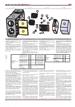
- Maintenance and repair should only be per-
formed by experienced and trained staff.
- The fan should be inspected and cleaned if
needed at least once a year.
- Be sure the fan is disconnected from power
source before performing any maintenance
or repair.
- Proceed to maintenance and repair after any
rotation in the fan stopped.
- Observe staff safety regulations during main-
tenance and repair.
- The motor is of heavy duty ball bearing con-
struction. The motor is completely sealed and
requires no lubrication for the life of the motor.
- Detach fan from the unit.
- Impeller should be specially checked for
buil-up material or dirt which may cause an
imbalance. Excessive imbalance can lead to ac-
celerated wear on motor bearings and vibration.
- Clean impeller and inside housing with mild
detergent, water and damp, soft cloth.
- Do not use high pressure cleaner, abrasives,
sharp instruments or caustic solvents that may
scratch or damage housing and impeller.
- Do not plunge impeller into any fluid.
- Make sure, that impeller’s balance weights
are not moved.
- Make sure the impeller is not hindered.
- Mount the fan back into the unit. Replace
fan guards and connect the fan to power sup-
ply source.
- If after maintenance or repair the fan does not
start either thermal protection contact activates
automatically, contact the manufacturer.
- During the maintenance do not hold the fan by
the impeller, it might cause disbalance of impeller
or damage it. Hold the fan by the casing.
- Montage und Elektroarbeiten nur durch aus-
gebildetes und eingewiesenes Fachpersonal
und nach den jeweils zutreffenden Vorschriften
ausführen.
- Die Anlage muss min. einmal pro Jahr geprüft
und gereinigt werden.
- Vor der Wartung oder Reparatur sicherstellen,
dass die Anlage vom Stromnetz getrennt ist.
- Arbeiten dürfen nur bei abgeschaltetem und
mechanischem Stillstand des Laufrades sowie
nach Abkühlung der Heizung vorgenommen
werden! Gegen Wiedereinschalten sichern!
- Arbeitssicherheitsregelungen bei der tech-
nischen Bedienung beachten.
- In der Motorkonstruktion sind hochwertige
Lager eingebaut. Die Lager sind eingepresst
und erfordern keine Schmierung.
- Ventilator von der Anlage abschalten.
- Die Flügel vom Ventilator auf Ablagerungen
und Staub prüfen, starke Verschmutzung kann
zu Unwucht führen. Die Unwucht verursacht
eine Vibration und schnelleren Lagerverschleiß.
- Flügel und Gehäuse mit einem sanften Rei-
nigungsmittel abwaschen, keine aggressiven
Putzmittel verwenden die das Material angreifen
könnten. Flügel und Gehäuse danach mit viel
Wasser gründlich reinigen, keine Hochdruck-
anlage, Putzmittel, scharfes Werkzeug oder
aggressive Stoffe verwenden, die zu Kratzer
und Beschädigungen führen könnten.
- Beim Reinigen der Flügel Motor vor Feuch-
tigkeit und Nässe schützen.
- Prüfen, dass die Wuchtgewichte am Flügel
nicht verschoben werden.
- Flügel darf nicht am Gehäuse streifen.
- Montieren des Ventilators wieder in die An-
lage. Anschließen die Anlage ans Stromnetz.
- Sollte sich nach Wartung der Anlage der
Ventilator nicht mehr einschalten lassen oder
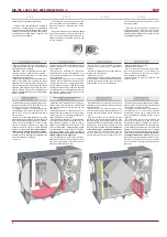
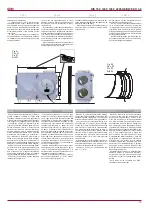
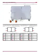
Unplug unit from mains first and wait for 2
minutes (till fans fully stop) before opening
the covers.
Bevor die Gerätetüren geöffnet werden dürfen,
Gerät elektrisch vom Versorgungsnetz trennen
und etwa 2 Min. warten, bis die Ventilatoren
völlig stehen bleiben.
Prima di aprire lo sportello del dispositivo stac-
care l’alimentatore della corrente e aspettare
che la rotazione dei ventilatori si arresti com-
pletamente (2 min. circa).
Перед тем, как открывать дверцу агрегата,
отключите агрегат от электросети и подожди-
те, пока вентиляторы остановятся полностью
(около 2 мин.).
Dirt increases air resistance in the filter, there-
fore less air is supplied into the premises.
- It is advisable to change the filters every 3-4
months, or in accordance with the readings of
filter contamination sensor. (Sensor PS 600 is
integrated in the unit).
Verunreinigte Filter erhöhen die Druckverluste,
d.h. ein geringeres Luftvolumen gelangt in die
Räume.
- Die Filter werden ca. alle 3 Monate bzw. je
nach Signal der Filterüberwachung ersetzt. (Der
Fühler PS 600 ist im Aggregat integriert).
I filtri sporchi incrementano le perdite di carico,
viene quindi immessa una minore quantità di
aria nei locali.
- È consigliabile sostituire i ogni 3-4 mesi op-
pure basandosi sulle indicazioni del sensore di
saturazione dei (il sensore PS 600 è montato
nel dispositivo).
Грязные фильтры повышают сопротивление
воздуха в нем, по этой причине в помеще-
ние попадает меньшее количество воздуха.
- Фильтр рекомендуется поменять на новый
каждые 3-4 месяца или по показаниям датчи-
ка загрязнения фильтров (датчик PS 600 инте-
грирован в агрегат).
- Работы по обслуживанию должны прово-
диться только опытными и квалифицирован-
ными специалистами.
- Осмотр и работы по обслуживанию долж-
ны проводиться не реже 1 раза в 6 месяцев.
- Сооблюдайте правила техники безопас-
ности проводя работы по обслуживанию
или ремонту.
- Перед началом работ по обслуживанию
или ремонту убедитесь, что вентилятор от-
ключен от питания.
- Приступайте к работам по обслуживанию
или ремонту только убедившись, что в вен-
тиляторе остановилось любое механиче-
ское движение.
- Подшипники запрессованы не требуют об-
служивания на весь срок службы двигателя.
- Отсоедините вентилятор от агрегата.
- Тщательно осмотрите крыльчатку венти-
лятора. Покрытие пылью или пр. материала-
ми может нарушить балансировку крылчатки.
Это вызывает вибрацию и ускоряет износ под-
шипников двигателя.
- Крыльчатку следует чистить не агрессив-
ными, коррозию крылчатки и корпуса не вы-
зывающими моющими средствами и водой.
- Для чистки крыльчатки запрещаетса ис-
пользовать струю высокого давления, абра-
зивные материалы, острые предметы и агрес-
сивные расстворители, способные поцара-
пать или повредить крыльчатку вентилятора.
- Во время чистки не погружайте крыльчат-
ку в жидкость.
- Убедитесь, что балансировочные грузики
крылчатки на своих местах.
- Убедитесь, что крылчатка не прикосает-
са к корпусу.
- Установите вентилятор обратно в агрегат
и подключите к электросети.
- Solo personale esperto e qualificato può ef-
fettuare lavori di manutenzione straordinaria.
- Il ventilatore deve essere ispezionato visiva-
mente e pulito almeno una volta all’anno.
- Prima di effettuare i lavori di manutenzione e
di riparazione assicurarsi che il dispositivo sia
scollegato dalla rete elettrica.
- Effettuare i lavori di manutenzione solo quan-
do tutte le parti del ventilatore si sono fermate.
- Durante i lavori di manutenzione tecnica, at-
tenersi alle opportune disposizioni di sicurezza
sul lavoro.
- Nel corpo del motore sono inseriti i cuscinetti
ad alta efficienza. Sono sigillati e non richiedo-
no alcuna lubrificazione per tutta la durata della
vita del motore.
- Scollegare il ventilatore dall’unità.
- È necessario ispezionare accuratamente la
ventola del ventilatore, controllando altre che
non si sia accumulata della polvere o aitre so-
stanze che potrebbero sbilanciare la ventola.
Lo sbilanciamento provoca vibrazioni e accele-
ra l’usura dei cuscinetti del motore.
- Pulire la ventola e la parte interna del corpo
con acqua e detergente delicato non corrosivo.
- Per pulire la ventola non utilizzare apparec-
chi ad altapressione, prodotti abrasivi, strumen-
ti appuntiti e solventi aggressivi che possono
graffiare o danneggiare la ventola.
- Durante la pulizia della ventola non immerge-
re motore nell’acqua.
- Assicurarsi che i pesi di bilanciamento della
ventola siano nella loro sede.
- Assicurarsi che la ventola non sfreghi contro
il corpo dell’unità.
- Reinserire il ventilatore nel dispositivo. Colle-
gare alla rete elettrica.
- Se dopo la manutenzione il ventilatore non si
accende oppure il termocontatto di protezione
den Einrichtungsbeschädigungen durch Feuch-
tigkeits-bzw. Wassereinwirkung entstehen.
Das Gerät kann bis auf -40 ° C nur mit dem
Vorheizregister betrieben werden, die Außen-
lufttemperatur muss bis auf -3 ° C vorerwärmt
werden. Ohne Vorheizregister kann das Gerät
nur bis bis auf -3,5 ° C Aussentemperatur arbei-
ten, wenn Frostschutzstrategie nach Algorithmus
Toutside oder Frostschutzstrategie Klingb nach
berechnetem Frostpunkt verwedet wird. Klingb
Froststrategie berechnet das mögliche Einfrieren
des Wärmetauschers gemäß der Ablufttempe-
ratur aus dem Raum, Raumabluftfeuchte und
Aussenlufttemperatur.
Das Gerät wegen Frostgefahr und zu niedri-
gen Zulufttemperaturen wird vorübergehend
gestoppt. Das Gerät schaltet sich ein, wenn
die Voraussetzungen für das Einfrieren des
Wärmetauschers weg sind. Werkseinstellung
nach schaltet sich das Gerät jede 3 Stunden
für ca. 5 Minuten in höchster Stufe ein um zu
prüfen, ob die Voraussetzungen für Einfrieren
des Wärmetauschers weg sind.
Wenn die Voraussetuzngen für das Einfrieren
des Wärmetauschers weg sind, dann arbeitet
das Gerät weiter wie vorher eingestellt. Wenn
die Voraussetzngen für das Einfrieren des
Wärmetauschers nicht weg sind, dann wird das
Gerät nach 5 Minuten bis zur nächsten Überprü-
fung gestoppt. Wenn während der Prüfung die
Zulufttemperatur unter eingestellter Temperatur
runterfällt, dann wird das Gerät nach 3 Minuten
gestoppt.
Anzeige auf dem Bedienteil nur dann ver-
schwindet, wenn das Gerät in Normalbetrieb
zurückkommt.
air pre-heater, which must warmed outdoor air
up to -3 ° C temperature. Without outdoor air
pre-heater, the unit will work only to -3.5 ° C
when using the Toutside anti-frost algorithm or
the calculated freezing temperature if Klingb
anti-frost algorithm is used. The Klingb anti-
frost algorithm calculates the potential freezing
temperature of the heat exchanger according
room air temperature, room humidity and outdoor
air temperature.
The unit is temporarily stopped due to the risk
of freezing the heat exchanger or because of
the low supply air temperature, the unit starts up
itself when the freezing risk disappear. Factory
that every 3 hours the unit starts up for ~ 5 min.
at the highest speed and check didn’t disap-
peared heat exchanger frost risk. If the reasons
have disappeared, the unit will work normally
at the speed that was set before the frost risk.
If the reasons have not disappeared, the unit
after 5 min. is temporarily stopped until the next
inspection. If during the test the temperature of
the supply air falls below the set limit, the unit is
stopped after about 3 minutes.
The message on the screen disappears only
when the unit goes into normal mode.
колем/водой.
В случае несоблюдения этих вышепере-
численных требований изготовитель име-
ет право не применять гарантию в отноше-
нии появившейся влаги/ воды в испорчен-
ных компонентах.
До -40°C температуры наружного возду-
ха агрегат можно использовать с электриче-
ским преднагревателям. Электрический пред-
нагреватель температуру наружного воздуха
поднимает до -3°C. Без электрического пред-
нагревателя агрегат будет работать до -3,5°C
когда включен алгоритм зашиты от замерза-
ния теплообменника «Toutside» или до рас-
считанной температуры когда включен алго-
ритм зашиты от замерзания теплообменни-
ка «Klingb». Алгоритм «Klingb» по температу-
ре и влажности вытяжного воздуха и по тем-
пературе наружного воздуха рассчитыва-
ет возможную температуру замерзания те-
плообменника.
Агрегат прекращает подачу свежего возду-
ха из за риска замерзания теплообменника
или низкой температуры наружного воздуха,
в противоположном случае агрегат возобнов-
ляет подачу свежего воздуха.
Заводские настройки по умолчанию: каж-
дые 3 часа агрегат на максимальной скоро-
сти вентиляторов возобновляет подачу воз-
духа на 5 минут. В данный момент проверя-
ется условия по «Toutside» алгоритму. Если
в момент проверки температура приточно-
го воздуха упадает ниже 15°C, тогда агрегат
прекращает подачу воздуха через 3 минуты.
Когда агрегат переходит в нормальный ра-
бочий режим сообщение на пульте дистанци-
онного управление выключается.
a 3°C. In assenza di batteria antigelo sulla pre-
sa di aria esterna, l’unità può operare soltanto
con temperatura fino a -3,5° C quando è attivo
il sistema antigelo basato sulla temperatura
esterna oppure quello basato sull’algoritmo
Klingenburg per il calcolo della temperatura
di formazione del ghiaccio. Questo algoritmo
calcola la temperatura presunta di formazione
del ghiaccio nello scambiatore basandosi sulla
temperatura ed U.R. dell’aria estratta e sulla
temperatura dell’aria esterna.
L’unità viene fermata momentaneamente quan-
do si presenta il rischio di gelo a causa della
temperatura di immissione troppo bassa e poi
viene riavviata quando il rischio di gelo viene
meno. Per verificare se tale rischio esista an-
cora o meno, ogni tre ore l’unità si avvia alla
massima velocità e opera per 5 minuti. Qualora
le condizioni siano tornate favorevoli, il recu-
peratore ricomincerà a funzionare al regime di
rotazione dei ventilatori impostato precedente-
mente dall’utente. Se, al contrario, le condizioni
non sono tornate favorevoli, l’unità si fermerà
nuovamente fino al successivo ciclo di prova.
Se durante tale ciclo la temperatura dell’aria
immessa dovesse scendere sotto il limite im-
postato dalla fabbrica, l’unità verrebbe fermata
dopo circa 3 minuti.
Un messaggio che avverte della procedura an-
tigelo in atto appare sul pannello di comando
remoto e scompare soltanto quando il funzio-
namento torna ad essere quello normale.


