Salda RIS 700HE/HW EKO 3.0 Скачать руководство пользователя страница 23

23

[ lt ]

[ ru ]

[ en ]

[ de ]

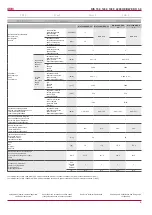
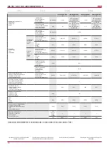
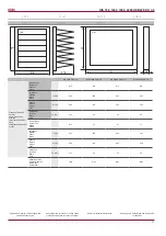
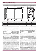
RIS 700_1200_1900_2200 HE/HW EKO 3.0

I collegamenti elettrici devono essere effettuati 

solo da un elettricista qualificato, in conformità 

alle disposizioni vigenti nazionali ed internazio-

nali sulla sicurezza elettrica e sull’installazione 

degli impianti elettrici.

Usare esclusivamente fonti di energia elettrica 

compatibili  con  i  dati  sono  indicati  sulla  targa 

presente sull’involucro del dispositivo.

Scegliere  il  cavo  di  alimentazione  in  funzio-

ne  ai  parametri  elettrici  del  dispositivo.  Se  la 

linea  di  alimentazione  dell’impianto  è  distante 

dall’unità,  è  necessario  tenere  conto  della  di-

stanza e del calo della tensione.

É necessaria la messa a terra dell’unità.

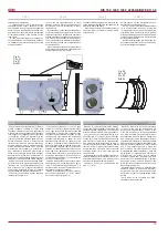
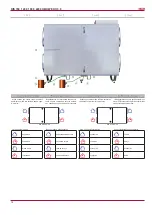
• Fissare il pannello di controllo nel luogo pre-

visto.

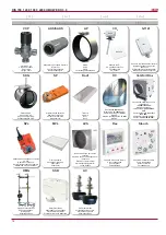
Con il cavo di connessione fornito insieme al 

pannello Flex collegare il pannello di controllo 

all’unità HVAC. E’ consigliabile di installare se-

paratamente dai cavi di potenza.  

Nota:

  se  insieme  al  cavo  si  usano  aitri  cavi 

di potenza, bisogna usare un cavo schermato 

per il  pannello con schermo collegato a terra.

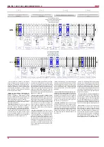
Inserire  il  connettore  (tipo  RJ10)  nella  sede 

dell’unità  RS485-1.  Inserire  l’  connettore  del 

cavo nel pannello di controllo.

Электрическое подключение может быть вы-

полнено  только  квалифицированным  элек-

триком в соответствии с действующими меж-

дународными и национальными требовани-

ями к электробезопасности, к монтажу элек-

трооборудования.

Использовать только источник электроэнер-

гии с такими данными, какие указаны на на-

клейке изделия.

Кабель  питания  должен  подбираться  по 

электрическим параметрам устройства, если 

линия питания устройства находится далеко 

от агрегата, необходимо учитывать расстоя-

ние и падение напряжения.

Устройство должно быть заземлено.

Смонтируйте  пульт  управления  в  выбран-

ном месте.

Протяните входящий в комплектацию FLEX 

контроллерa  кабель  подключения  между 

пультом управления и агрегатом ОВКВ. Пульт 

дистанционного  управления  рекомендуется 

монтировать отдельно от силовых кабелей.

Примечание:

 если кабель используете вме-

сте с другими силовыми кабелями, должен ис-

пользоваться экранированный кабель пульта 

с заземленным экраном.

Подключите  штепсель  (тип  RJ10)  к  гнезду 

агрегата RS-485-1. Другой штепсель кабеля 

подключите к пульту управления.

Electrical connection can only be implemented 

by the qualified electrician in accordance with 

the applicable international and national electri-

cal  safety  requirements  and  requirements  for 

installation of electrical devices.

Use only power source which meets the require-

ments specified on the device label.

Power supply cable should be selected based 

on the electrical specification of the device. If the 

device power supply line is far from the unit, the 

distance and voltage drop should be considered.

Device must be earthed.

Install the control panel at the designated place.

Install  the  supplied  connection  cable(FLEX 

controller)  between  the  control  panel  and  the 

HVAC  unit.  It  is  recommended  to  install  the 

control panel separately from the power cables.

Note:

 If cable is used together with other power 

cables, shielded control panel cable with earthed 

shield should be used.

Connect the plug (RJ10 type) to the RS485-1 

socket of the unit. Connect the other end to the 

control panel.

Elektrischer Anschluss muss durch qualifizierte 

Elektrofachkraft  laut  geltende  internationale 

und nationale Bestimmungen für Elektroschutz 

und Einrichtung der Elektroanlagen ausgeführt 

werden.

Nur die Stromquelle gebrauchen, die auf dem 

Anlagenaufkleber angegeben ist.

Speisekabel muss laut elektrischen Parametern 

der Anlage gewählt werden; falls die Speiselei-

tung der Anlage fern vom Aggregat ist, ist es nö-

tig, den Abstand und Spannungsfall zu bewerten.

Die Anlage muss unbedingt geerdet werden.

Steuerpult muss auf dem vorgesehenen Platz 

montiert werden.

Anschlusskabel(FLEX), der ein Teil der Ausrüs-

tung ist, muss zwischen dem Steuerpult und dem 

HKLK-Aggregat gelegt werden. Empfehlenswert 

wird der Bedienpult getrennt von den Leistungs-

kabeln montiert werden

Bemerkung:

  wenn  der  Kabel  mit  anderen 

Leistungskabeln  gebraucht  wird,  muss  ein 

abgeschirmtes  Pultkabel  mit  der  geerdeten 

Abschirmarmierung gebraucht werden.

Den Stecker (Typ RJ10) an die Aggregatsdose 

RS485-1 anschließen. Den anderen Kabelste-

cker an den Steuerpult anschließen.
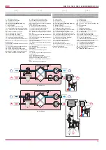
RS458_1 RS458_2

23

Textract

04h_Read_Input

2

1

[ it ]

 - Valore del sensore della temperatura dell’aria  estratta

[ ru ]

 - Значение температурного датчика удаляемого воздуха

[ en ]

 - Exhaust air temperature sensor value

[ de ]

 - Wert des Abluft-Temperatursensors

Hex: E0

24

ToutDoor

04h_Read_Input

3

1

[ it ]

 - Valore del sensore della temperatura dell’aria esterna

[ ru ]

 - Значение температурного датчика наружного воздуха

[ en ]

 - Ouside air temperature sensor value

[ de ]

 - Wert des Außenluft-Temperatursensors

Hex: FFEC

25

Twater

04h_Read_Input

12

1

[ it ]

 - Valore del sensore della temperatura dell’acqua di ritorno

[ ru ]

 - Значение температурного датчика обратной воды

[ en ]

 - Return water temperature sensor value

[ de ]

 - Wert des zurückkehren Wasser-Temperatursensors

Hex: FFEC

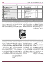
NOTA: si può collegare e (o) scollegare il pan-

nello di controllo remoto solo dopo aver scolle-

gato l’unità HVAC dalla fonte di alimentazione.

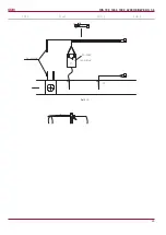
Attivare la tensione di alimentazione, attivare 

l’interruttore di sicurezza Q,vedi fig. 5 (l’aspetto 

dell’interruttore  può  essere  diverso  dalla  foto 

(ciò dipende dal modello del prodotto).

ПРИМЕЧАНИЕ:

 подключить и (или) отклю-

чить пульт дистанционного управления мож-

но, только отключив питание агрегата ОВКВ.

Включите напряжение питания, включите за-

щитный рубильник Q (см. 

рис. 5

 [рубильник 

может отличаться от изображения на фото в 

зависимости от модели изделия]).

NOTE:

 The remote control panel can be con-

nected and (or) disconnected only after discon-

necting the power supply for the HVAC unit.

Switch  on  the  mains  voltage,  switch  on  the 

blade switch Q, see 

Fig. 5

 (actual appearance 

of  the  blade  switch  can  be  different  from  the 

given photo based on the model of the product).

BEMERKUNG:

 Fernbedienpult kann nur nach 

der Abschaltung  der  Speisung  fürs  HKLK-

Aggregat angeschlossen und/oder abgeschlos-

sen werden.

Speisespannung und Schutzmesserschalter Q 

einschalten. (Siehe 

Abb. 5

 (die wahre Ansicht 

des Messerschalters kann sich von dem im Foto 

wiedergegebenen Messerschalter in Abhängig-

keit vom Produktmodel unterscheiden).)

OFF

ON

Fig. 5

Рис. 5

Fig. 5

Abb. 5

Usando  il  pannello  di  controllo  remoto,  sce-

gliere la velocità dei ventilatori desiderata e la 

temperatura dell’aria di mandata.

Пользуясь  дистанционным  пультом  управ-

ления,  выберите  желаемую  скорость  вра-

щения вентиляторов и температуру приточ-

ного воздуха.

Select  the  desired  fan  rotation  speed  and 

the  supply  air  temperature  using  the  remote 

controller.

Während des Gebrauchs vom Fernbedienpult 

werden  die  gewünschte  Drehgeschwindigkeit 

der  Ventilatoren  und  die  Zulufttemperatur  ge-

wählt werden.

Содержание RIS 700HE/HW EKO 3.0

Страница 1: ...ubject to technical modification RIS 700_1200_1900_2200 HE HW EKO 3 0_P0017_AP_0002 Manuale di uso e manutenzione it ru Technical manual en Bedienungsanleitung de CENTRALE DI VENTILAZIONE CON RECUPERO...

Страница 2: ...AVS 16 Unit di controllo 16 Protezione del sistema 18 Uso dell unit un una rete BMS 19 Indirizzi ModBus 20 Connessione elettrica dell unit HVAC 21 Guida per la riparazione del sistema 22 Guasti princ...

Страница 3: ...nection diagram 32 Product maintenance table 34 Inhalt Transport und Lagerung 4 Beschreibung 4 Schutzmassnahmen 4 Bestandeile des Ger tes 5 Betriebsbedingungen 5 Bedienung 6 Filter 6 Ventilator 6 W rm...

Страница 4: ...protect the product during shipping It is recommended to remove the protective film after the shipping otherwise the product may get signs of oxidation Alle Ger te sind werksseitig so verpackt dass s...

Страница 5: ...st grunds tzlich verboten Arbeiten des Elektroanschlusses unter Spannung durchzuf h ren Wenn die Anschlussklemmen abgeschaltet sind ist das Schutzniveau IP00 So kann man Komponente ber hren die die ge...

Страница 6: ...con temperatura dell aria esterna di 40 C soltanto con una batteria elettrica antigelo che porti la temperatura fino 23 5 40 C 1 24 h It is recommended to use electrical pre heater if the supply air t...

Страница 7: ...della vita del motore Scollegare il ventilatore dall unit necessario ispezionare accuratamente la ventola del ventilatore controllando altre che non si sia accumulata della polvere o aitre so stanze...

Страница 8: ...rom the heater and remove the heater Pic a b Das Elektro Heizregister bedarf keiner zus tz lichen Wartung Es sind nur die Filter rechtzeitig zu wechseln wie oben aufgef hrt Heizregister verf gen ber 2...

Страница 9: ...nale di controllo control input Steuerungsignal VDC 0 10 0 10 classe di protezione protection class Schutzart IP 44 IP 54 Potenza assorbita generale Total power consumption Total Leistungsaufnahme pot...

Страница 10: ...ontrol input Steuerungsignal VDC 0 10 classe di protezione protection class Schutzart IP 54 Potenza assorbita generale Total power consumption Total Leistungsaufnahme potenza corrente power current Ne...

Страница 11: ...imensioni dei Filtri Filter class and dimen sions Filterklasse und Abmes sungen Di estrazione Exhaust Abluft M5 M5 M5 M5 Larghezza Width Breite L mm 600 650 692 692 Altezza Height H he H mm 250 415 52...

Страница 12: ...d environment Installation must be performed in such manner that the weight of the air duct system and its com ponents would not overload the ventilation unit Enough space must be left during installa...

Страница 13: ...mounted below the AHU s 1 level Nach dem Montieren des WRG Ventilators 1 an der Wand mu das Ablaufsystem des Kondensats angeschlossen werden Dazu muss das Endst ck 2 am Kondensatablauf des WRG Ventil...

Страница 14: ...der Bedienseite aus betrachtet Fortluft Abluft Aussenluft Zuluft Depends on version of the ordered outdoor air can be taken from the left or right side L ftungsger te k nnen je nach bestellter Ver sio...

Страница 15: ...ensor for extract air M1 actuator of by pass damper PS1 supply air differential pressure switch PS2 extract air differential pressure switch PS3 Heat exchanger antifrost pressure swich TE Exhaust air...

Страница 16: ...00 K hler Warmwasserregister Kasten Comfort Box 400 SP Attuatore della serranda Actuator for dampers Klappenmotor 1141 SPs Attuatore della serranda con ritorno a molla Spring return actuator for dampe...

Страница 17: ...Pa 0 60 TJ T1 TV VV 2 M4 M5 24VAC 3 M6 Esempio Example Exempel La temperatura dell aria di mandata pu essere regolata in base alla temperatura mi surata dal sensore dell aria di mandata e alla tempera...

Страница 18: ...l von 0 10V DC bedient Funktion BOOST Die Ventilatoren werden mit einer maxima len Geschwindigkeit angelassen auf dem Bedienpult FLEX wird die BOOST Funktion dargestellt Die BOOST Funktion ist nicht a...

Страница 19: ...o il valore del regolatore PI inferiore al valore impostato vd paragrafo II 6 4 3 della descrizione Flex Ventilazione possibile impostare 3 tipi di ventilazione vd paragrafo II 6 3 della Flex in base...

Страница 20: ...anto non siano stati danneggiati Lo scatto della protezione termica automati ca solitamente avviene a causa di velocit del ventilatore troppo bassa ventilatore guasto serranda su presa d aria con attu...

Страница 21: ...1 1 Schaiter Interruttore 2 2 Switch 2 2 Schaiter 180 ON ON 470 ON OFF 330 OFF ON Abb 3 RS485_1 und RS485_2 RS485_1 Dose des Fernbedienpults RS485_2 ModBus Anschluss ON Ein Stouch Bedienteil muss an...

Страница 22: ...n Outside air damper actuator de Antrieb der Au enluftklappe 0 90 14 Preheater 01h_Read_Coils 12 1 it Indicazione della batteria di preriscaldamento ru en Preheater indication de Anzeige des Vorheizer...

Страница 23: ...metern der Anlage gew hlt werden falls die Speiselei tung der Anlage fern vom Aggregat ist ist es n tig denAbstand und Spannungsfall zu bewerten Die Anlage muss unbedingt geerdet werden Steuerpult mus...

Страница 24: ...ir TJ temp sensor 21 22 X16 6 11 12 13 14 15 16 17 N L 19 X16 5 M2 M3 17 18 L N N L L 16 20 15 230V AC 230V AC ON OFF ON OFF L control N L control L Supply air Extract air damper actuator damper actua...

Страница 25: ...25 lt ru en de RIS 700_1200_1900_2200 HE HW EKO 3 0 Set 5 o C...

Страница 26: ...315 mA pr fen Guasto dei connettori elettrici del dispositivo Possible unit fauit at electrical connections of the unit St rung in elektrischen Verbindungen Anschl ssen des Aggregats it Verificare pr...

Страница 27: ...ienpuit oder RG1 Regler auszutauschen Il i ventilatore ventilatori non funziona non funzionano Fan s not working Ventilator en nicht funktioniert Guasto del ventilatore dell aria immessa PV o quella e...

Страница 28: ...sul termostato Se la temperatura dell aria di mandata bassa controllare la centrale termica ru 1a 4 1 2a en Switch off the supply voltage Disconnect the respective sensor plug from the automation Meas...

Страница 29: ...29 lt ru en de RIS 700_1200_1900_2200 HE HW EKO 3 0...

Страница 30: ...o elettrica rotore Electric preheater rotor ON OFF 230V 50Hz Elektrovorheizer Rotor EIN AUS 230V 50Hz O 16A 100 X12 Tensione del ventilatore alla velocit attuale Voltage of Normal speed for air fans S...

Страница 31: ...hlers X33 3 VAL Apertura della valvola della batteria PWM 24v 50hz PWM 24v 50hz Cooling valve opening PWM 24v 50hz ffnen der K hlungsklappe PWM 24v 50hz AO X33 4 VAL Chiusura della valvola della batte...

Страница 32: ...ore della temperatura dell aria esterna Fresh ambient air temperature sensor Temperatursensor der frischen Luft der Au enluft X33 21 T OUT Sensore esterno Outdoor sensor Au ensensor AI X33 22 COM COM...

Страница 33: ...our factory is pre run and tested before leaving and is shipped in good working order and condition We therefore extend to the original purchasers the following Warranty for the period of two years fr...

Страница 34: ...16 3 ALARM X33 11 COM ANTI F Fan fall 1 2W max 4 5 6 10 9 X16 4 24 1 2W max Fan run 11 12 COM FAN 25 24 P 23 X29 X25 N L F1 3 1 P DX Cooling B 0 10 COM 14 11 G M5 24VAC 3 position Y2 Y1 VAL VAL VAL X3...

Страница 35: ...E PE N L PE N L PV GND 0 10V in X32 X33 CE7 7 X16 7 PE N L1 L1 N PE L1 N PE L1 N PE 1f 230V AC Power supply cable X16 36 36 28 25 20 22 23 24 24 23 22 23 24 X16 4 25 25 31 30 X16 7 29 34 33 32 35 36 3...

Страница 36: ...36 lt ru en de RIS 700_1200_1900_2200 HE HW EKO 3 0...

Страница 37: ...37 lt ru en de RIS 700_1200_1900_2200 HE HW EKO 3 0...

Страница 38: ...V Y2 Control CLOSE AC 24 V G System potential AC 24 V 24VDC X16 1 2 1 3 X33 5 X33 4 X33 3 VAL VAL VAL Y1 Y2 24VAC 3 position M5 G 11 14 COM B 0 10 4 5 6 7 X21 2 1 2 PS1 PS2 DX Cooling P 1 3 L N X25 X2...

Страница 39: ...PE L1 L2 L3 N PE 1 2 3 4 5 6 7 8 9 9 8 7 6 5 4 3 2 1 X4 X3 PE N L K1 11 K1 14 PV GND X32 10A F1 1 2 T set COM X33 23 X33 24 26 27 28 P Transmitter 2 24 VDC 26 24V DC 27 intput 0 10V DC 28 GND L1 PE N...

Страница 40: ...ituzione dei filtri Filter replacement Filterwechsel Ogni 3 4 mesi 3 4 Every 3 4 months Alle 3 4 Monate NOTA L acquirente del prodotto ha l obbligo di compilare la Tabella di manutenzione del prodotto...

Отзывы: