Removal and replacement of ADU modules
8-14
Chapter 8: Service & maintenance
98-137654-A
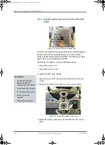
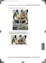
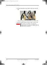
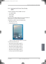
The ISM shall — based on request from the PCM — provide
information about movement of the parabolic reflector, in the
form of samples from gyro- and acceleration-sensors.
The ISM board is:
• Communication as slave of the ADU Bus connecting the
Inertial Sensor Module (ISM), the DC-motor Driver Modules
(DDM), the Polarization Motor Module (PMM), and the
Pedestal Control Module (PCM).
• Collection of contemporary sample-data sets from all sensors
and provide those to the PCM on request. A set of samples
should be collected within less than 100 micro seconds.
• High stability and accuracy 3 axis accelerometer and angular
rate sensor.
• Prepared for wide range 3 axis accelerometer.
• Calibration of sensor offset, gain, and misalignment over
temperature (stored in non-volatile memory).
• Secure fixing to the parabolic reflector.
• Diagnosis of board supplies, sensor inputs, etc.
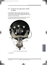
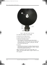
12. Elevation locking pin to lock the antenna dish in a fixed position
(for safety during service) (not visible on photo).
13. Pedestal Control Module (PCM).
The PCM will - based on several inputs - control the position of
the parabolic reflector and the polarization angle of the
polarisation mechanism assembly via 3 brush less DC-motors
and a stepper motor.
The PCM board is:
• Communication master of the ADU Bus connecting to the DC-
motor Driver Modules (DDM), the Polarization Motor Module
(PMM), and the Inertial Sensor Module (ISM).
• Communication with the GPS module.
• Provide power to the modules connected via the ADU bus
(motor drivers supplies and bus interface circuits' supplies)
with over-current protection (hot swap) via the bus cable.
• Modules are by means of shielded DB9 cables connected in a
chain in the following order: PCM — DDM (azimuth) — DDM (X-
elevation) — DDM (elevation) — ISM — PMM. PMM module
contains signal terminations.
14. Service switch.
In switch-off position the DC Motor Driver modules (DDM) and
the Polarisation Motor Module (PMM) are turned off for safe
conditions during service and repair. The switch must be in on
position for normal ADU operation. The switch only controls
SAILOR100TM.book Page 14 Tuesday, January 29, 2013 2:44 PM
Содержание 100
Страница 1: ...TRAINING INSTALLATION SERVICE MANUAL SAILOR 100 Satellite TV ...
Страница 2: ......
Страница 13: ...Table of contents 98 137654 A xi SAILOR100TM book Page xi Tuesday January 29 2013 2 44 PM ...
Страница 14: ...Table of contents xii 98 137654 A SAILOR100TM book Page xii Tuesday January 29 2013 2 44 PM ...
Страница 78: ...Power up 5 8 Chapter 5 Connecting power 98 137654 A SAILOR100TM book Page 8 Tuesday January 29 2013 2 44 PM ...
Страница 215: ...Appendices SAILOR100TM book Page 1 Tuesday January 29 2013 2 44 PM ...
Страница 216: ...SAILOR100TM book Page 2 Tuesday January 29 2013 2 44 PM ...
Страница 250: ...List of ACU events C 10 Appendix C System messages 98 137654 A SAILOR100TM book Page 10 Tuesday January 29 2013 2 44 PM ...
Страница 254: ...Glossary Glossary 4 98 137654 A SAILOR100TM book Page 4 Tuesday January 29 2013 2 44 PM ...
Страница 261: ......
Страница 262: ...info thrane com thrane com 98 137654 A ...

