Removal and replacement of ADU modules
98-137654-A
Chapter 8: Service & maintenance
8-27
8888
Ser
vic
e & m
ain
ten
anc
e
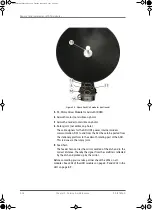
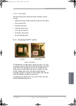
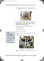
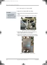
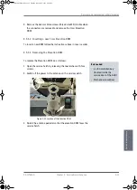
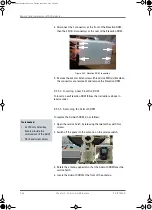
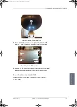
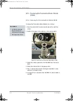
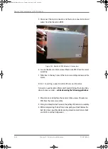
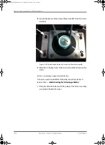
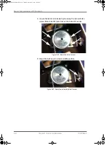
5. Disconnect the 3 connectors at the right of the Azimuth DDM,
then the 2 SUB-D connectors at the left of the Azimuth DDM.
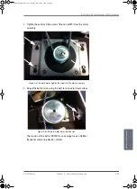
6. Remove the 4x4 mm Allen screws (thread size M5) (visible when
the connectors are removed) and remove the Azimuth DDM.
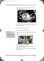
8.5.3.6 Inserting a new Azimuth DDM
To insert a new Azimuth DDM follow the instructions above in
reverse order.
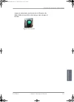
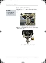
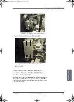
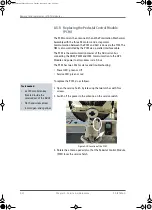
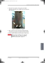
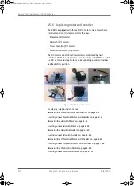
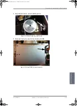
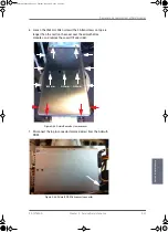
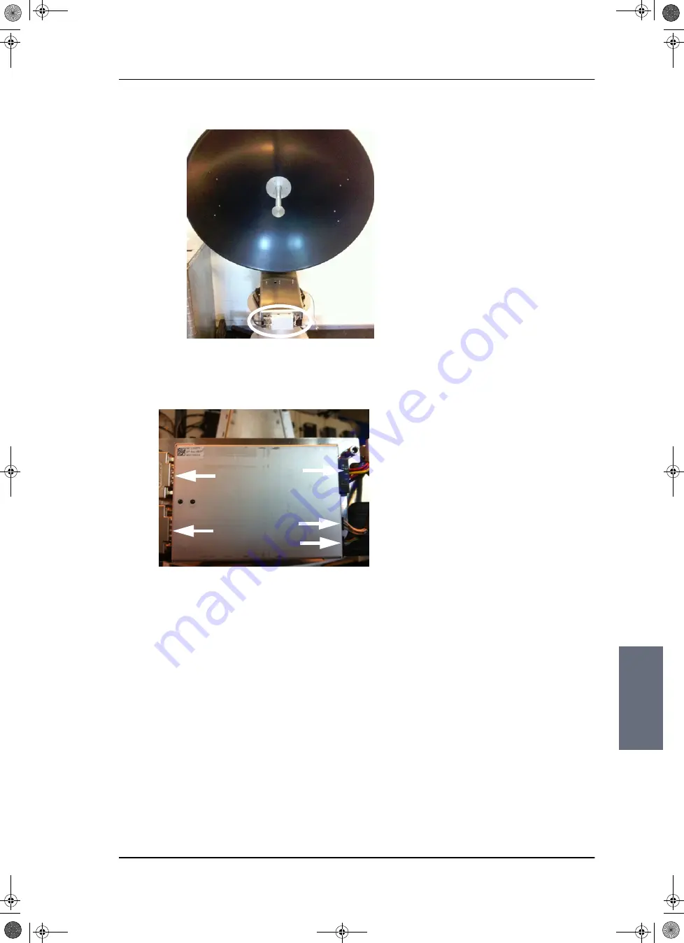
Figure 8-24: location of the Azimuth DDM
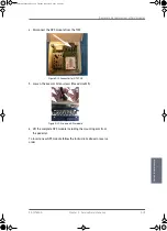
Figure 8-25: Azimuth DDM, connectors
SAILOR100TM.book Page 27 Tuesday, January 29, 2013 2:44 PM
Содержание 100
Страница 1: ...TRAINING INSTALLATION SERVICE MANUAL SAILOR 100 Satellite TV ...
Страница 2: ......
Страница 13: ...Table of contents 98 137654 A xi SAILOR100TM book Page xi Tuesday January 29 2013 2 44 PM ...
Страница 14: ...Table of contents xii 98 137654 A SAILOR100TM book Page xii Tuesday January 29 2013 2 44 PM ...
Страница 78: ...Power up 5 8 Chapter 5 Connecting power 98 137654 A SAILOR100TM book Page 8 Tuesday January 29 2013 2 44 PM ...
Страница 215: ...Appendices SAILOR100TM book Page 1 Tuesday January 29 2013 2 44 PM ...
Страница 216: ...SAILOR100TM book Page 2 Tuesday January 29 2013 2 44 PM ...
Страница 250: ...List of ACU events C 10 Appendix C System messages 98 137654 A SAILOR100TM book Page 10 Tuesday January 29 2013 2 44 PM ...
Страница 254: ...Glossary Glossary 4 98 137654 A SAILOR100TM book Page 4 Tuesday January 29 2013 2 44 PM ...
Страница 261: ......
Страница 262: ...info thrane com thrane com 98 137654 A ...

